| CSC373/406: 10 [10/13] | |
Figure 10.1: A system that uses physical addressing.
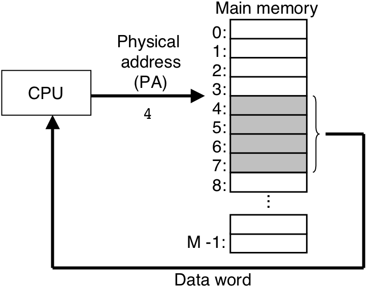
Figure 10.2: A system that uses virtual addressing.
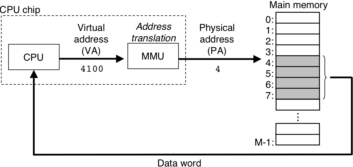
Figure 10.3: How a VM system uses main memory as a cache.
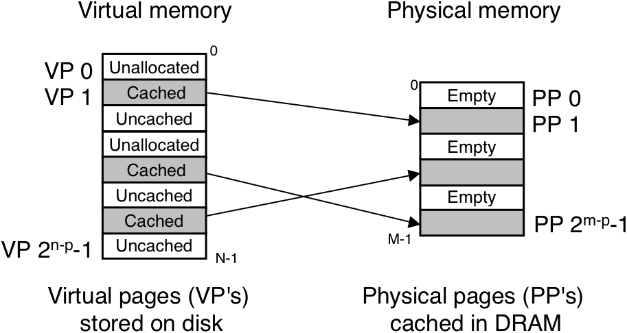
Figure 10.4: Page table.
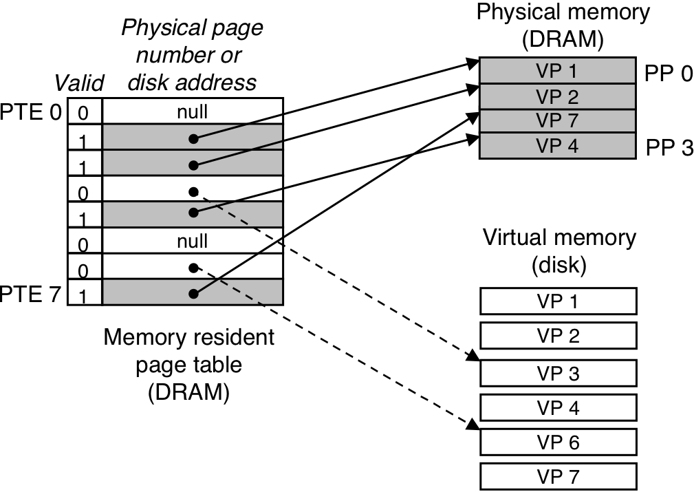
Figure 10.5: VM page hit.
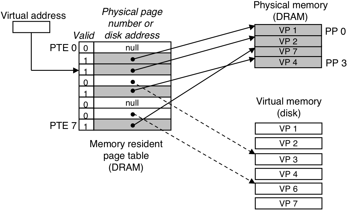
Figure 10.6: VM page fault (before).
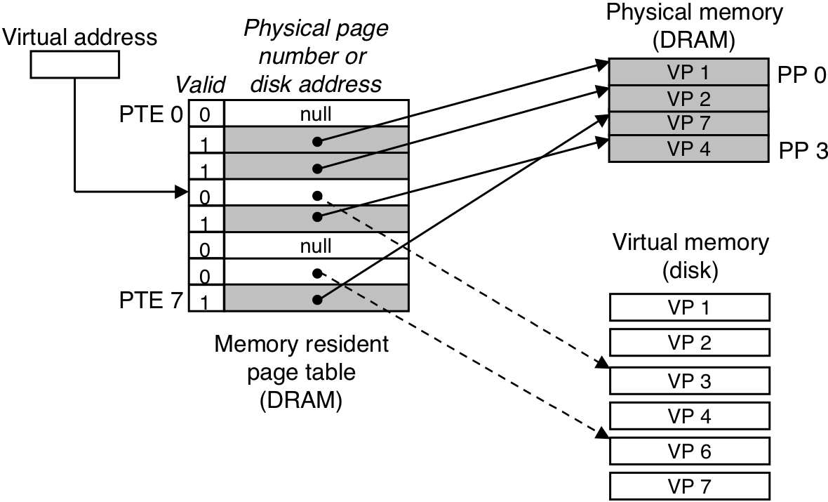
Figure 10.7: VM page fault (after).
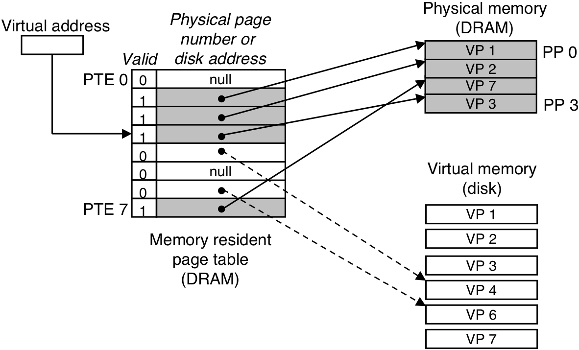
Figure 10.8: Allocating a new virtual page.
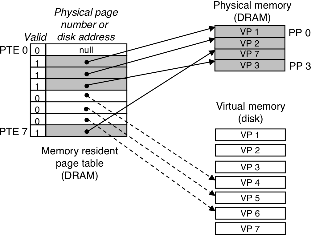
Figure 10.9: How VM provides processes with separate address spaces.
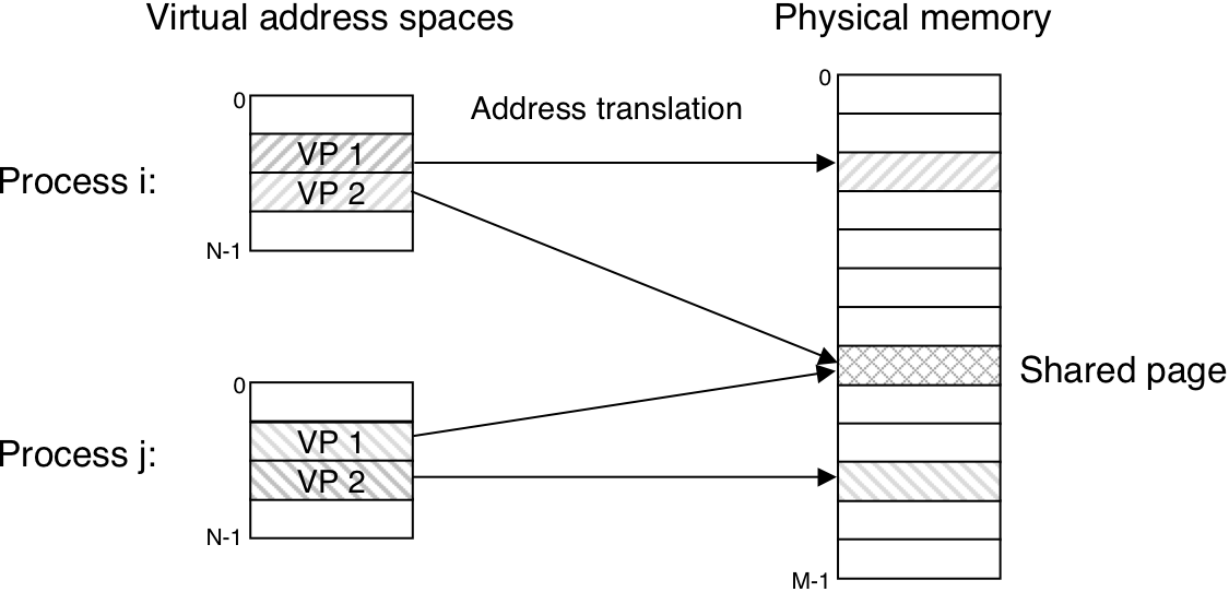
Figure 10.10: The memory image of a Linux process.
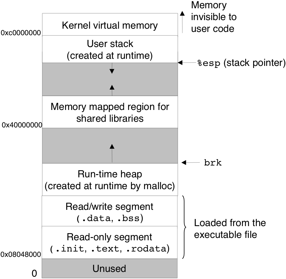
Figure 10.11: Using VM to provide page-level memory protection.
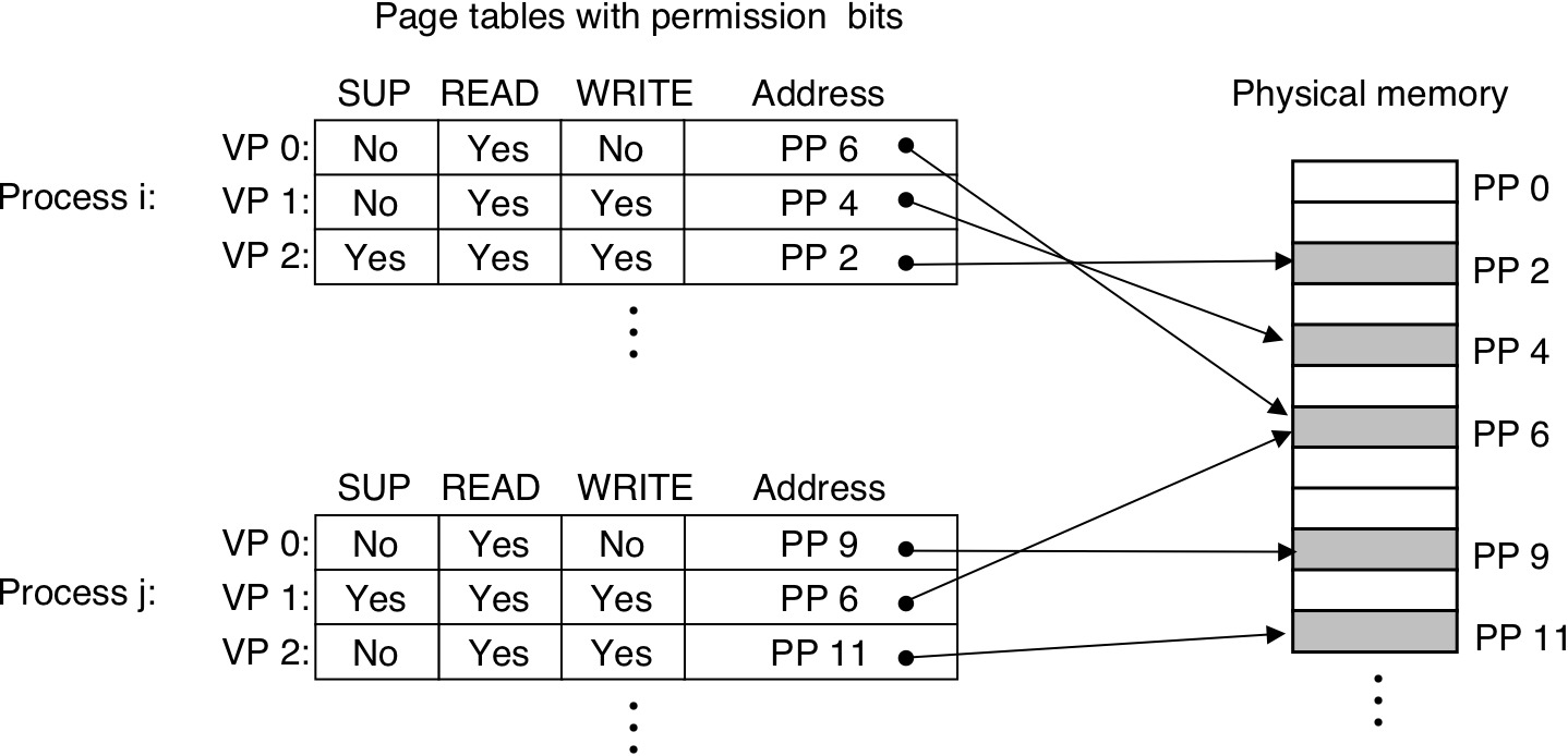
Figure 10.13: Address translation with a page table.
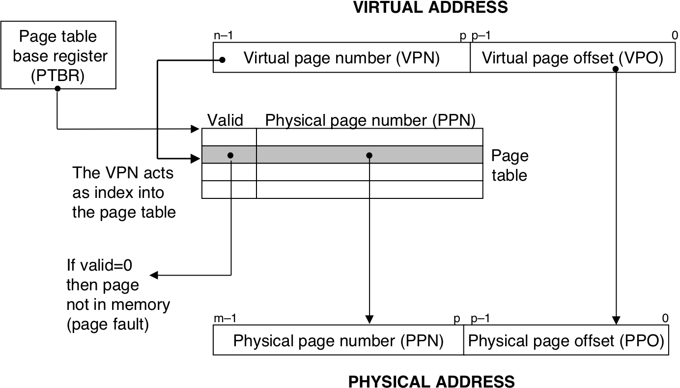
Figure 10.14: Operational view of page hits and page faults.
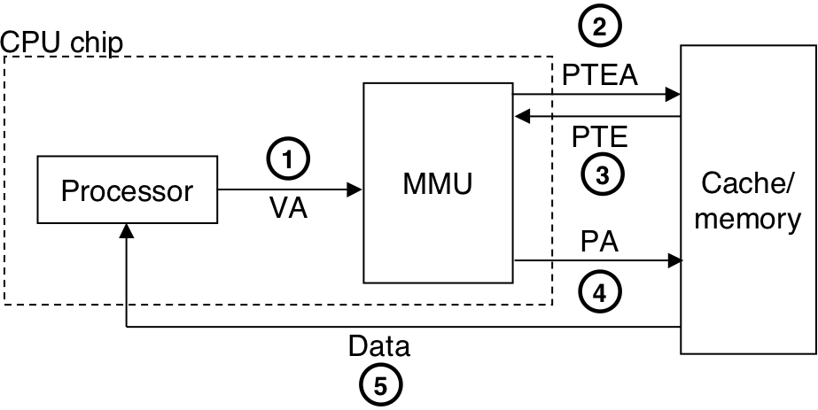
Figure 10.14: Operational view of page hits and page faults.
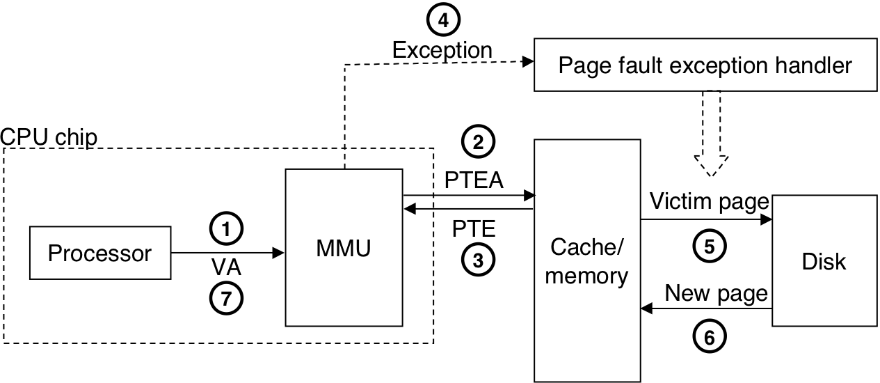
Figure 10.15: Integrating VM with a physically addressed cache.
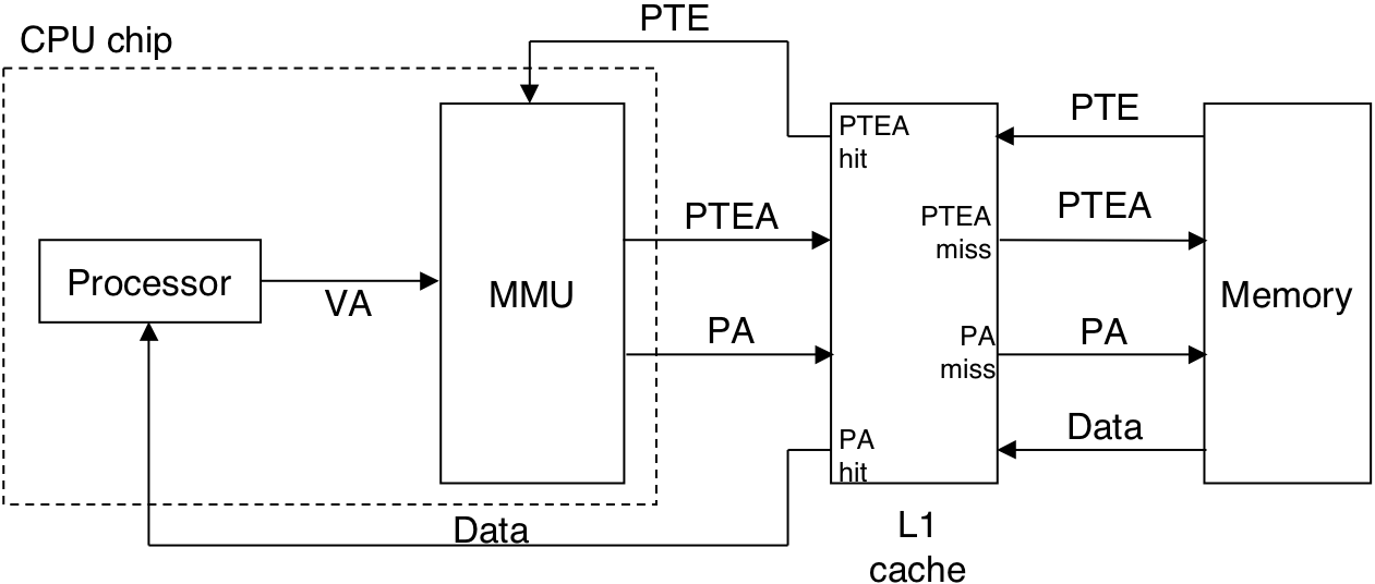
Figure 10.16: Components of a virtual address that are used to access the TLB.
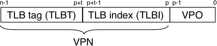
Figure 10.17: Operational view of a TLB hit and miss.
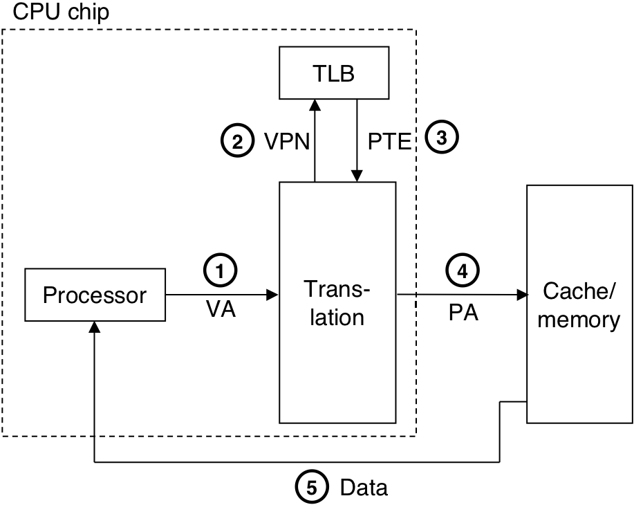
Figure 10.17: Operational view of a TLB hit and miss.
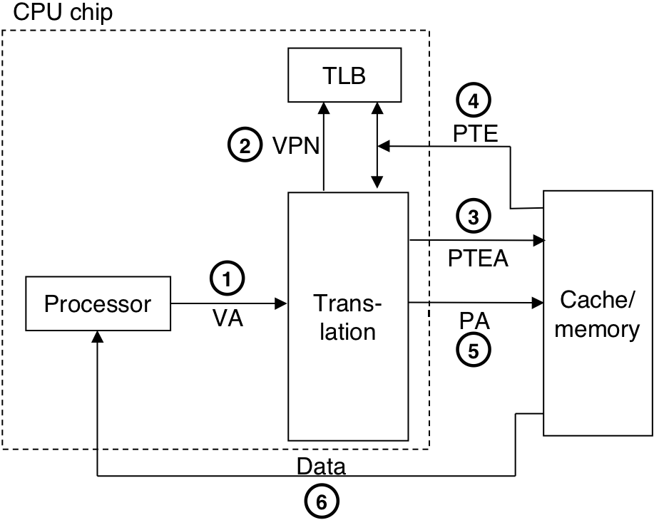
Figure 10.18: A two-level page table hierarchy.
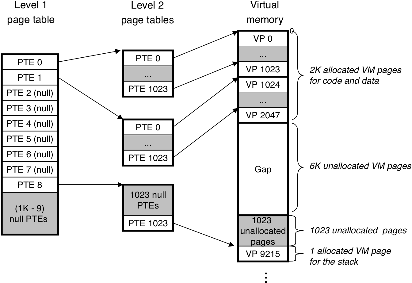
Figure 10.19: Address translation with a k-level page table.
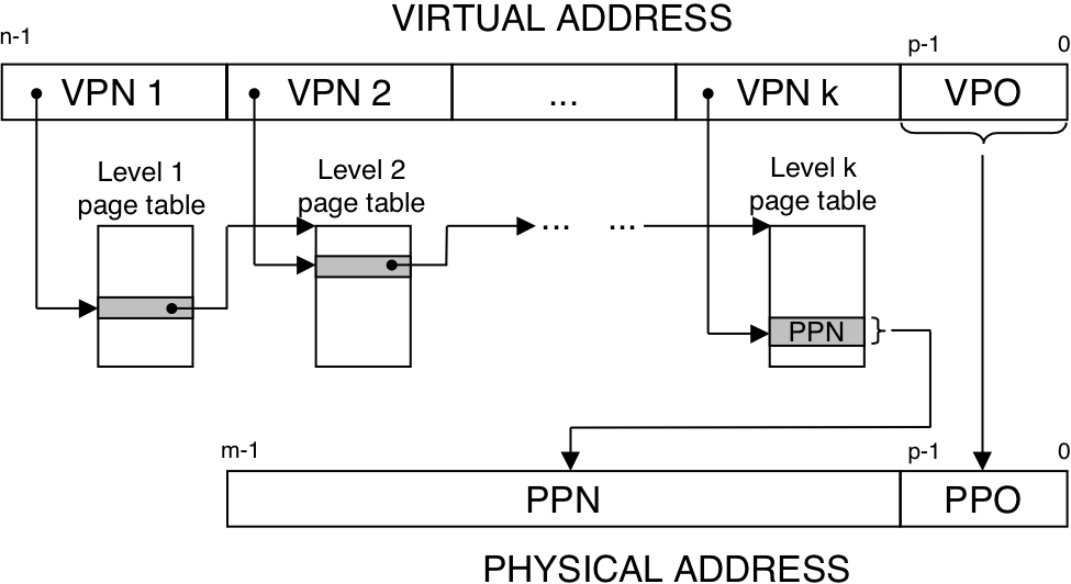
Figure 10.20: Addressing for small memory system.
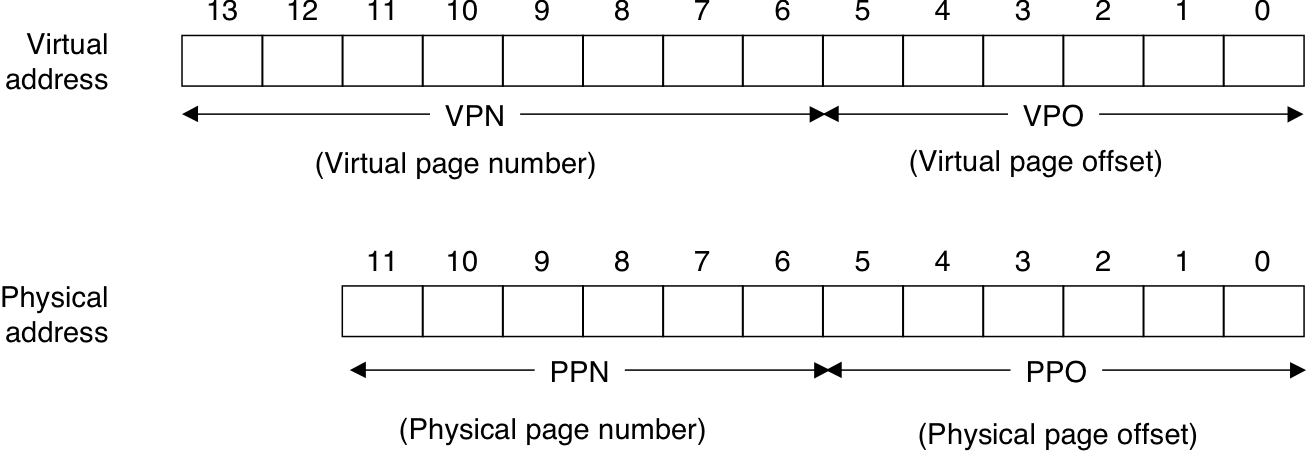
Figure 10.21: TLB, page table, and cache for small memory system.

Figure 10.21: TLB, page table, and cache for small memory system.
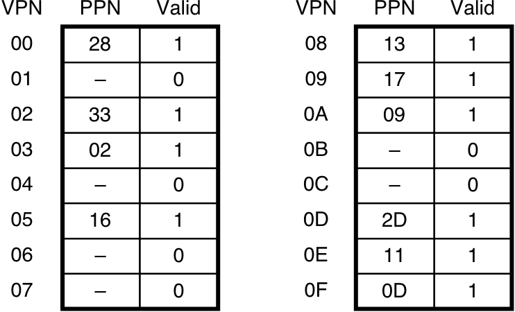
Figure 10.21: TLB, page table, and cache for small memory system.
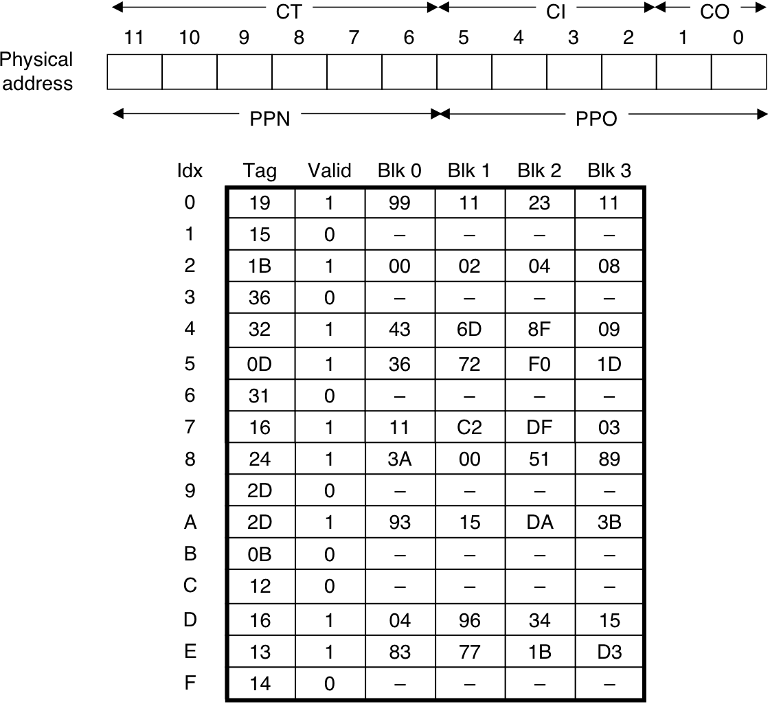
Figure 10.22: The Pentium memory system.
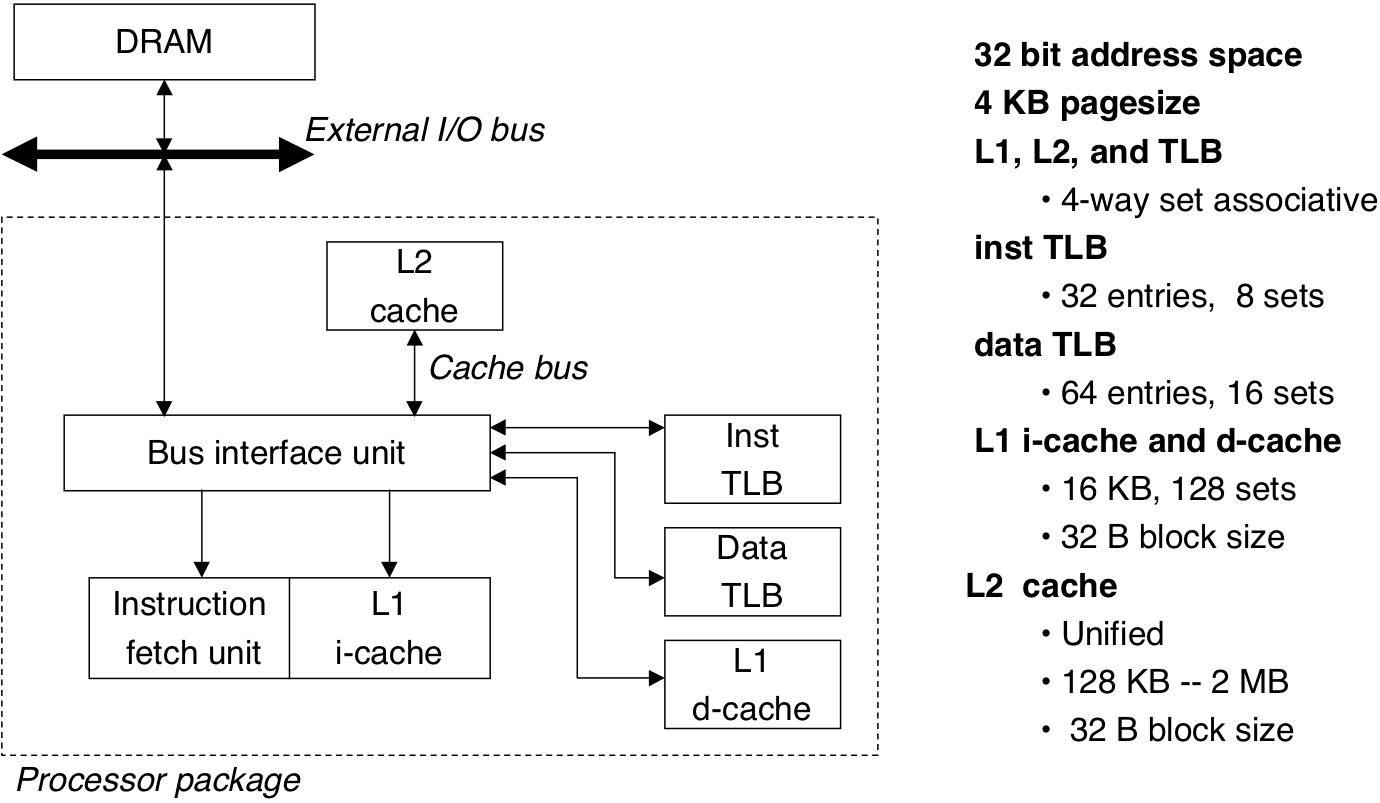
Figure 10.23: Summary of Pentium address translation.
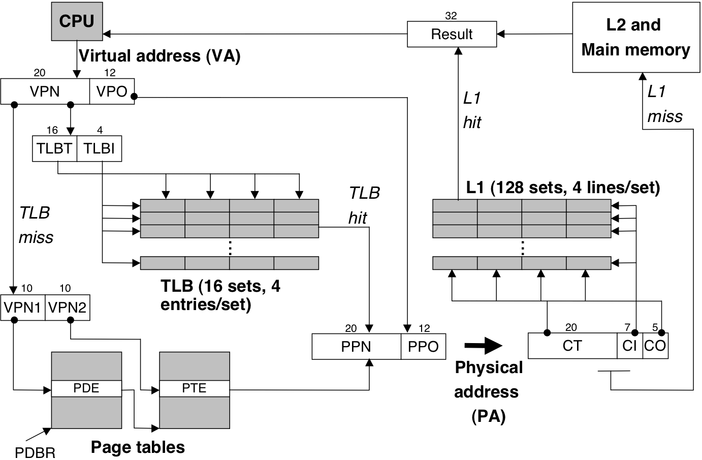
Figure 10.24: Pentium multi level page table.
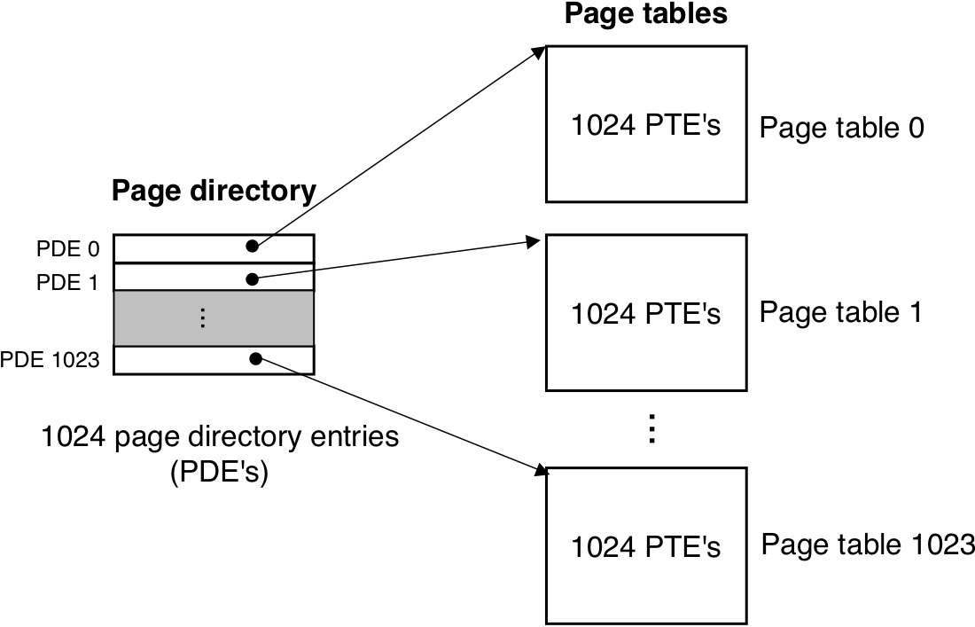
Figure 10.25: Formats of Pentium page directory entry (PDE) and page table entry (PTE).

Figure 10.25: Formats of Pentium page directory entry (PDE) and page table entry (PTE).
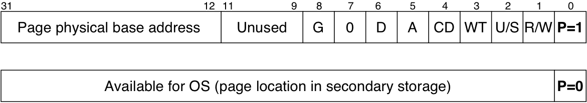
Figure 10.26: Pentium page table translation.
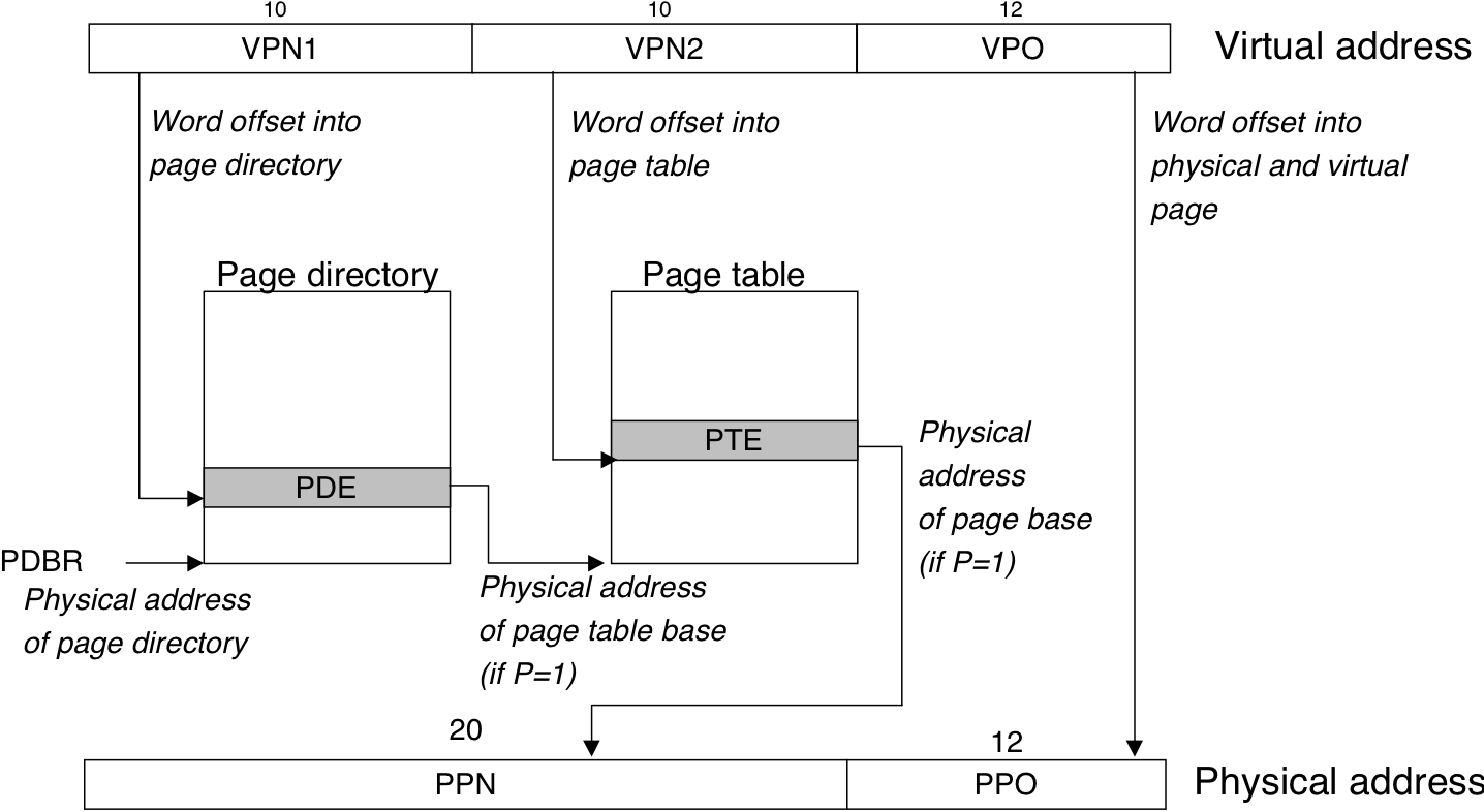
Figure 10.27: Pentium TLB translation.
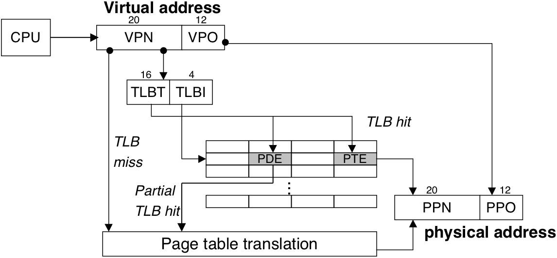
Figure 10.28: The virtual memory of a Linux process.
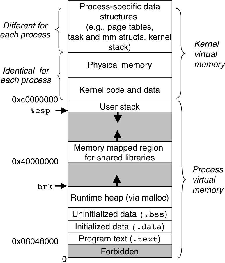
Figure 10.29: How Linux organizes virtual memory.
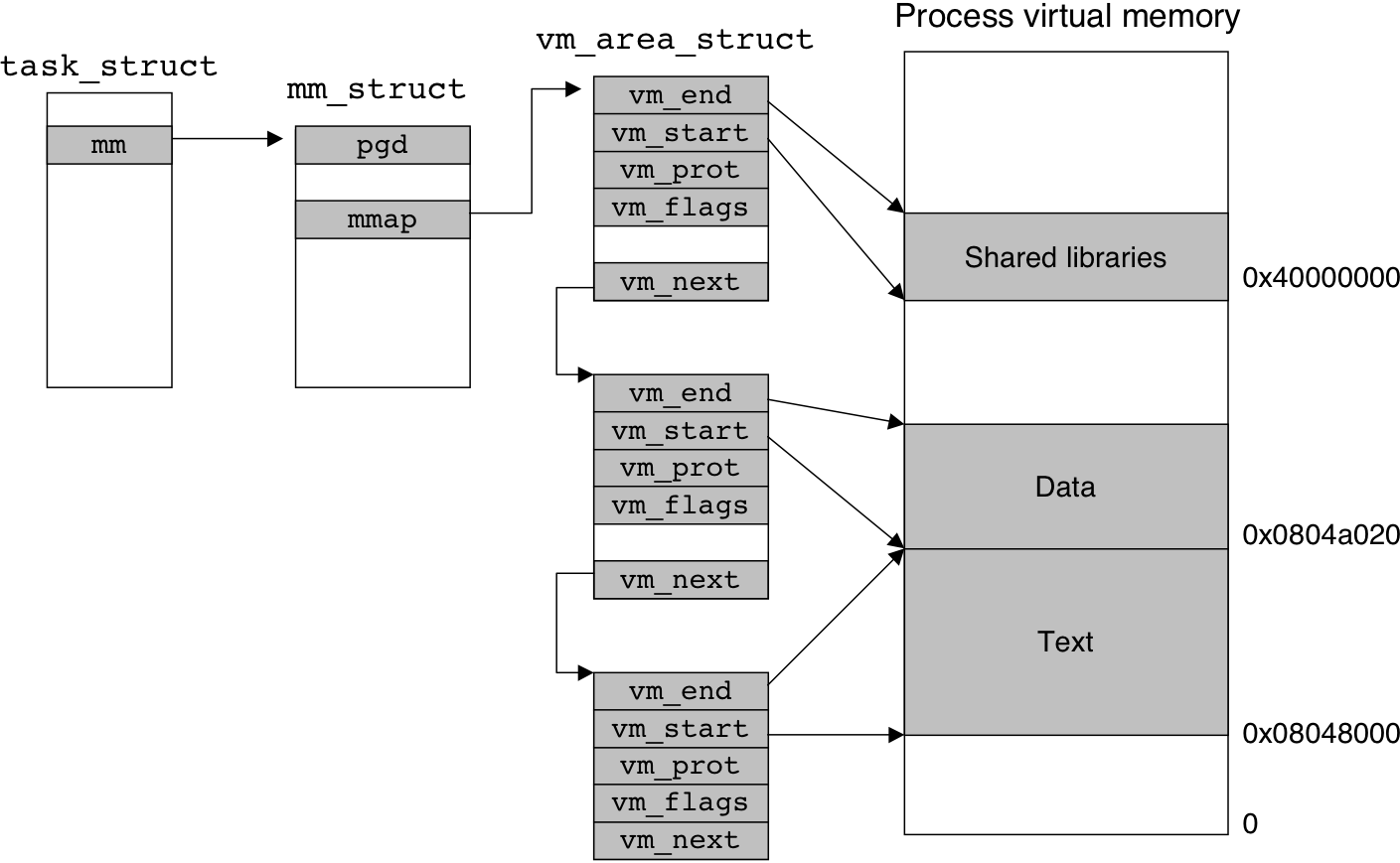
Figure 10.30: Linux page fault handling.
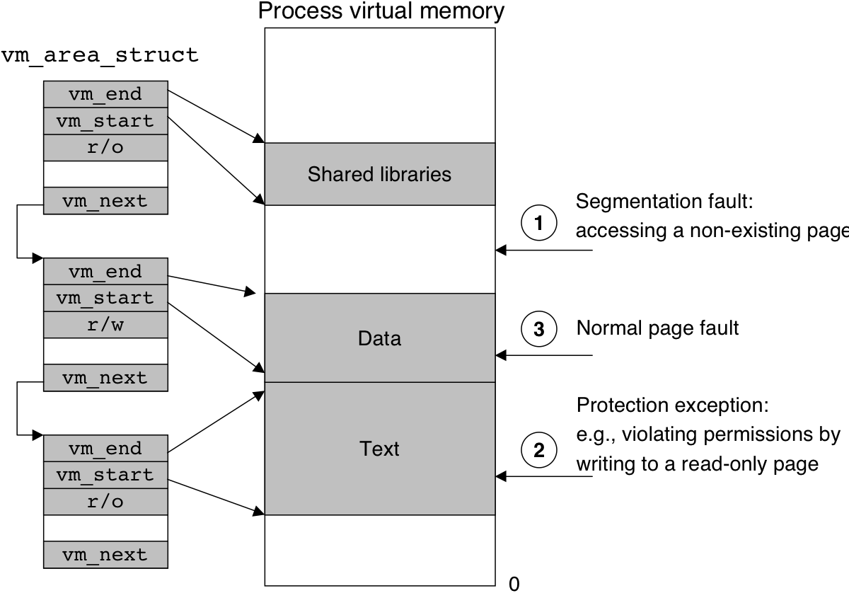
Figure 10.31: A shared object.
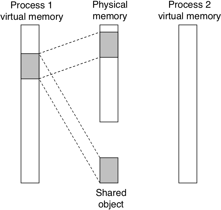
Figure 10.31: A shared object.
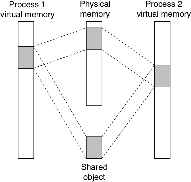
Figure 10.32: A private copy-on-write object.
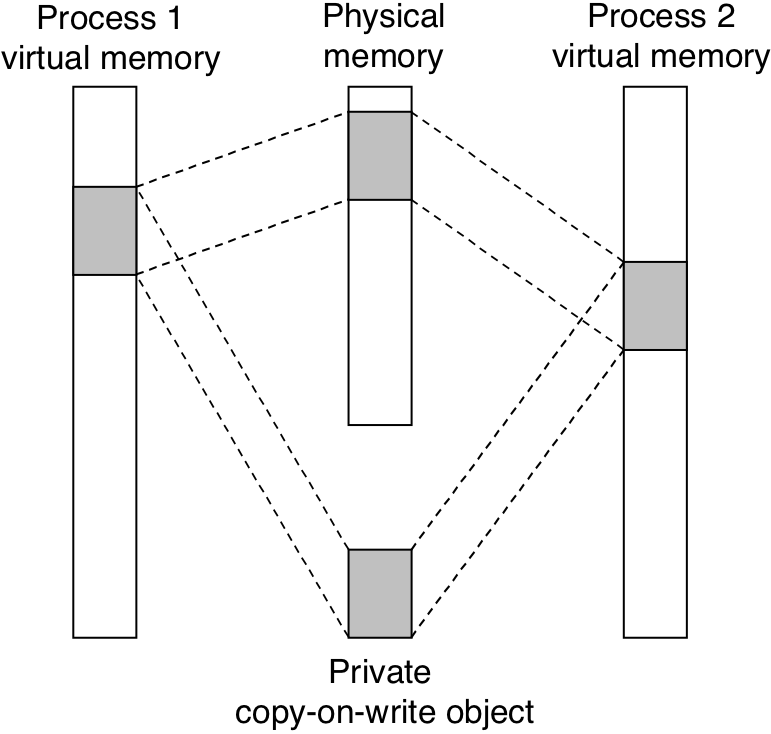
Figure 10.32: A private copy-on-write object.
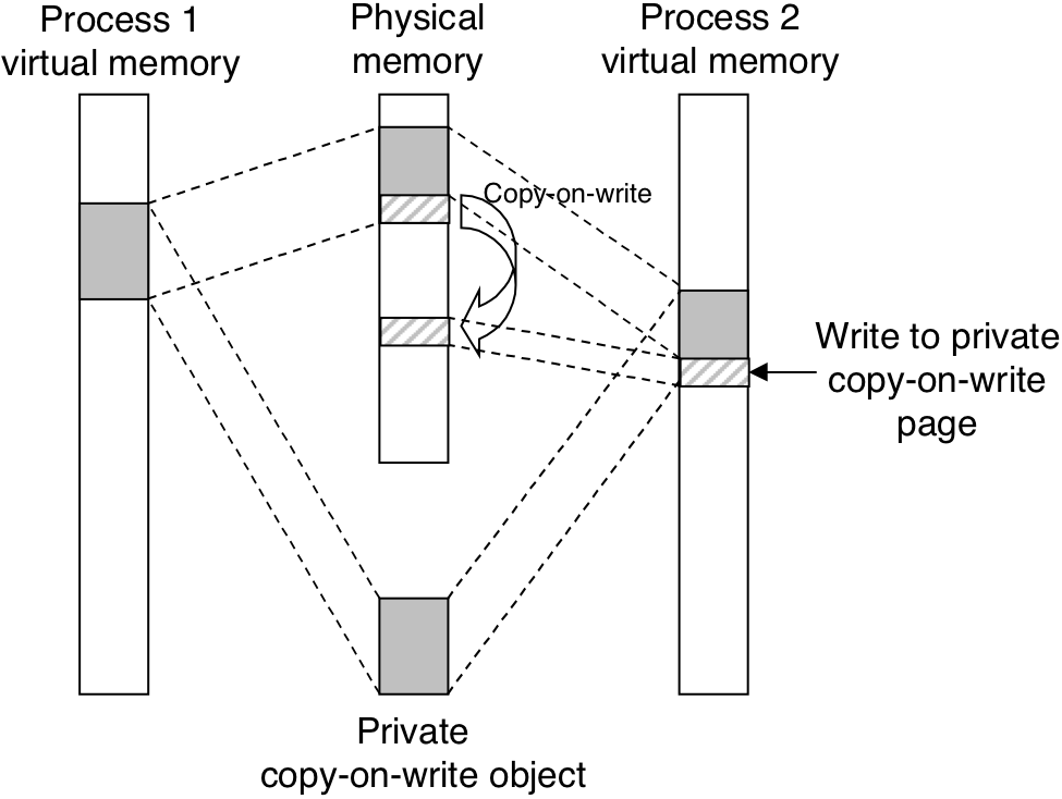
Figure 10.33: How the loader maps the areas of the user address space.
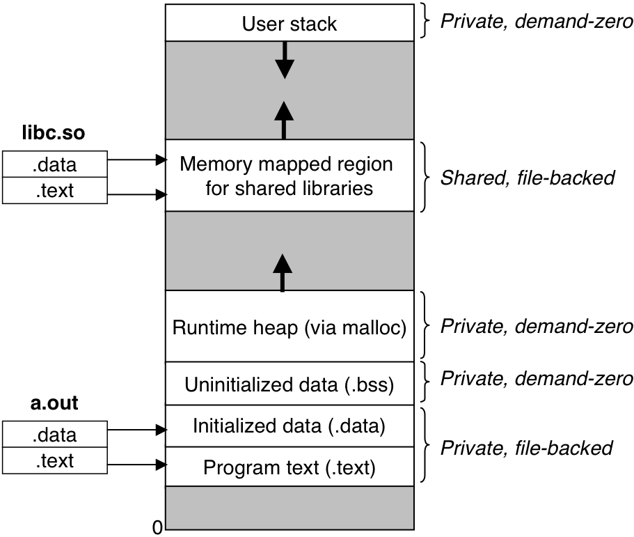
Figure 10.34: Visual interpretation of mmap arguments.
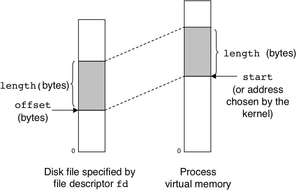
Figure 10.35: The heap.
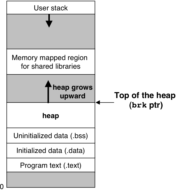
Figure 10.36: Allocating and freeing blocks with malloc.
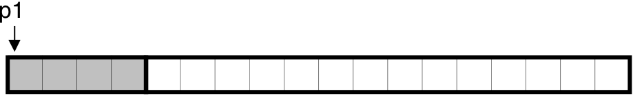
Figure 10.36: Allocating and freeing blocks with malloc.
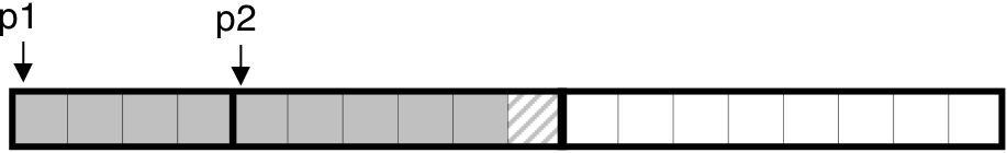
Figure 10.36: Allocating and freeing blocks with malloc.
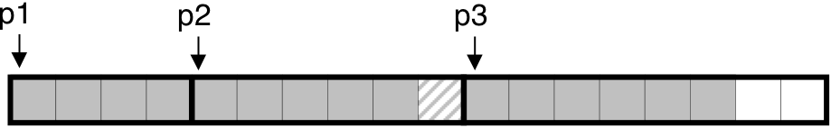
Figure 10.36: Allocating and freeing blocks with malloc.
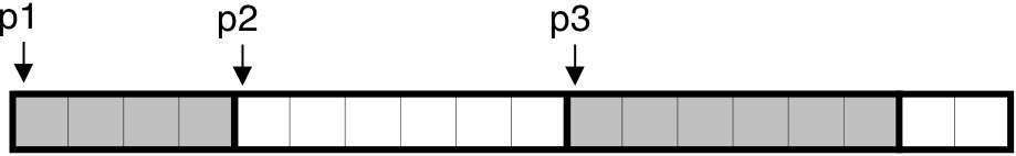
Figure 10.36: Allocating and freeing blocks with malloc.
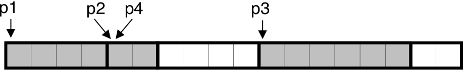
Figure 10.37: Format of a simple heap block.
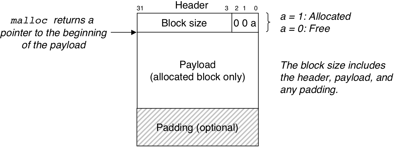
Figure 10.38: Organizing the heap with an implicit free list.
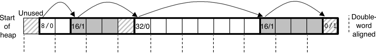
Figure 10.39: Splitting a free block to satisfy a three-word allocation request.
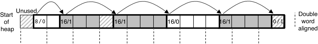
Figure 10.40: An example of false fragmentation.
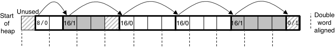
Figure 10.41: Format of heap block that uses a boundary tag.
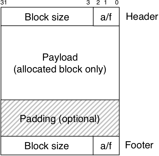
Figure 10.42: Coalescing with boundary tags.
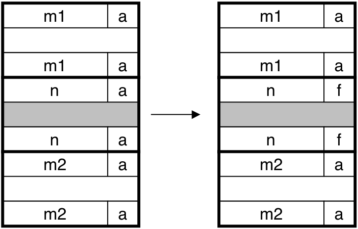
Figure 10.42: Coalescing with boundary tags.
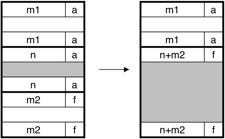
Figure 10.42: Coalescing with boundary tags.
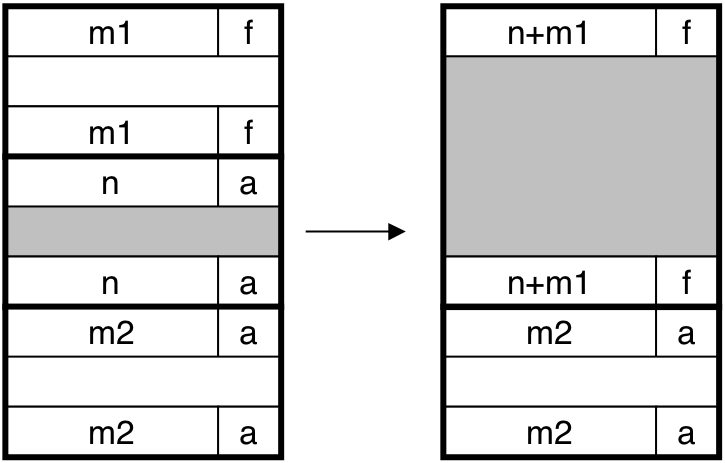
Figure 10.42: Coalescing with boundary tags.
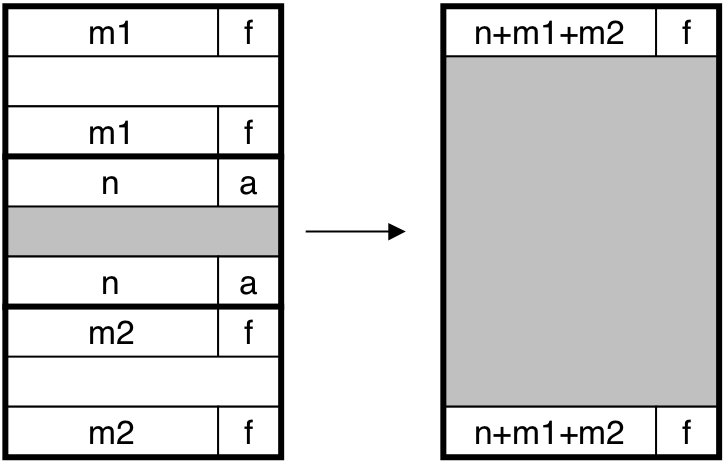
Figure 10.44: Invariant form of the implicit free list.
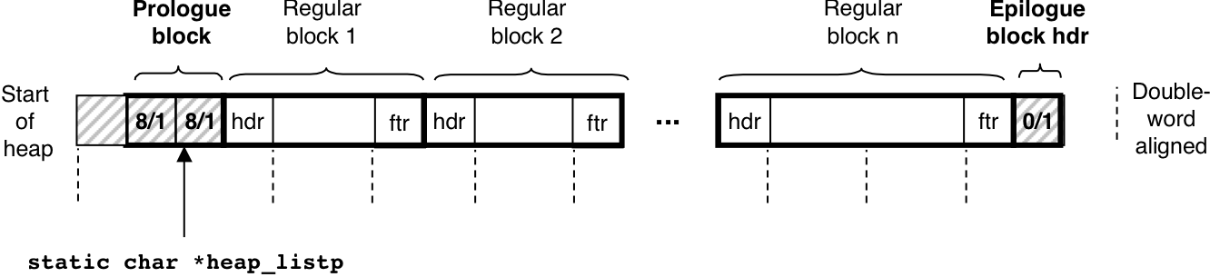
Figure 10.50: Format of heap blocks that use doubly-linked free lists.
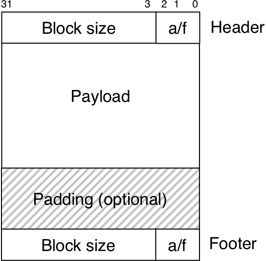
Figure 10.50: Format of heap blocks that use doubly-linked free lists.
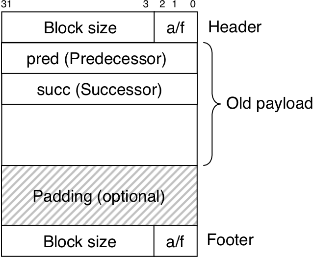
Figure 10.51: A garbage collector's view of memory as a directed graph.
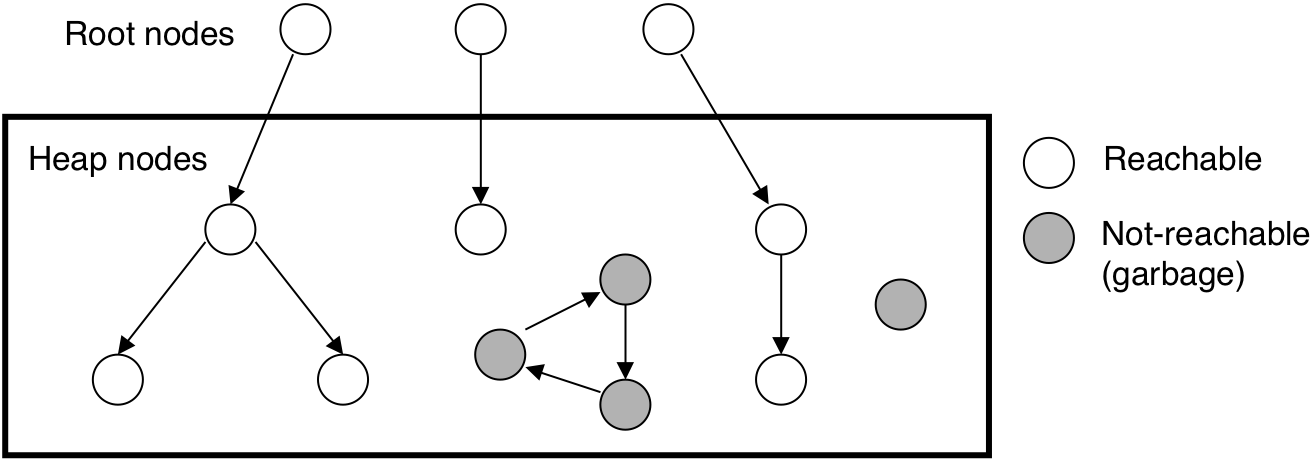
Figure 10.52: Integrating a conservative garbage collector and a C malloc package.
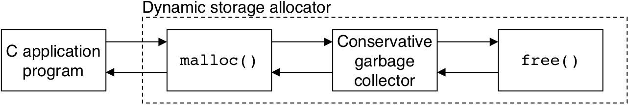
Figure 10.54: Mark and sweep example.
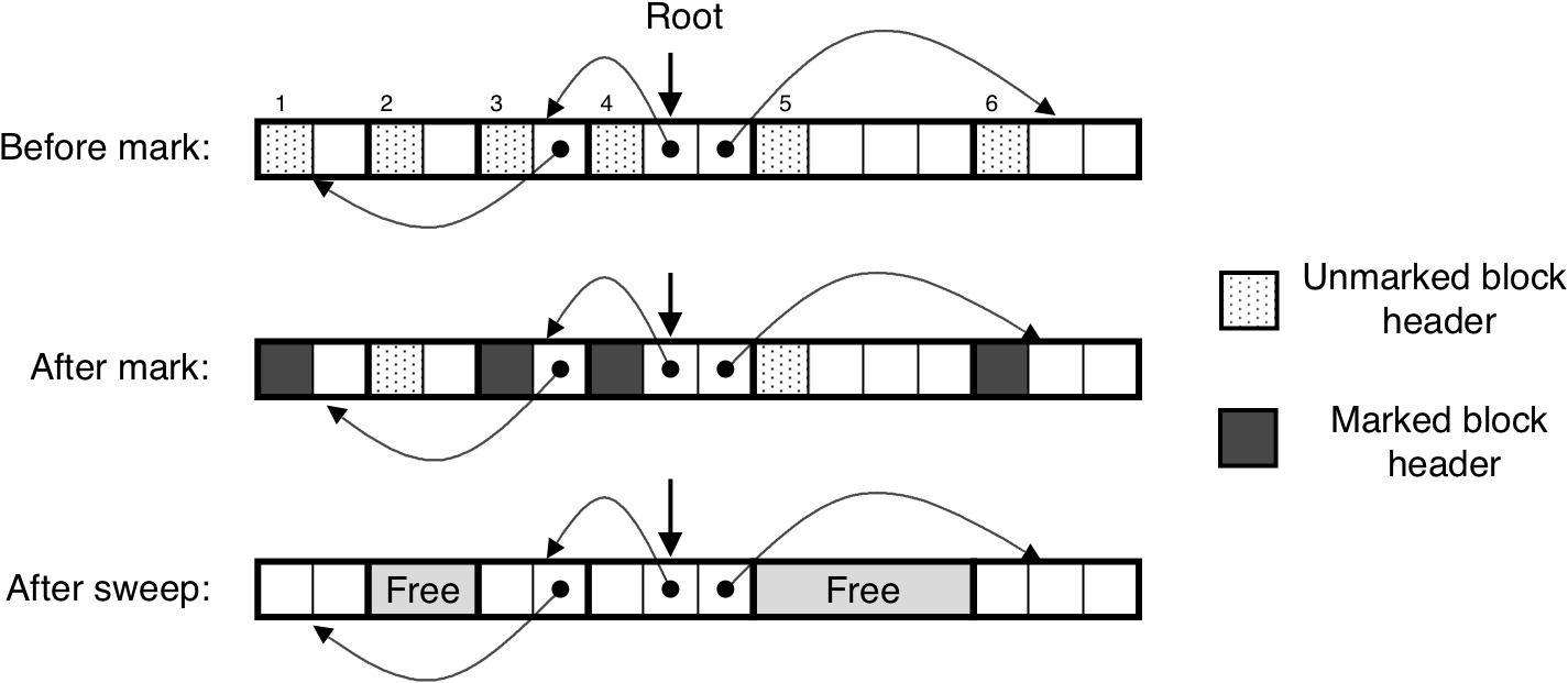
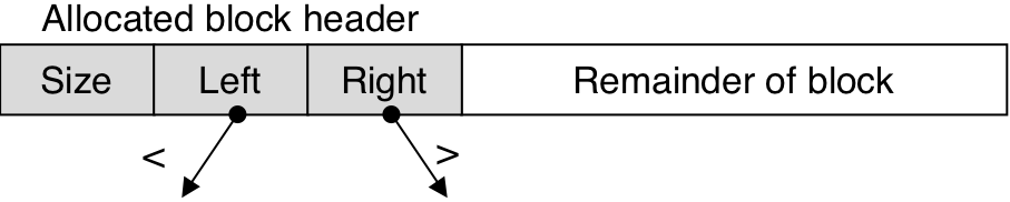
Figure 10.55: Left and right pointers in a balanced tree of allocated blocks.