| CSC373/406: 4 [4/13] | |
Figure 4.1: Y86 programmer-visible state.
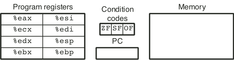
Figure 4.2: Y86 instruction set.
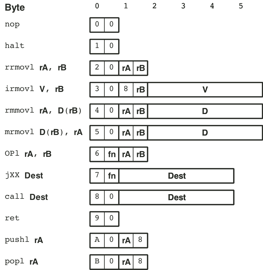
Figure 4.3: Function codes for Y86 instruction set.
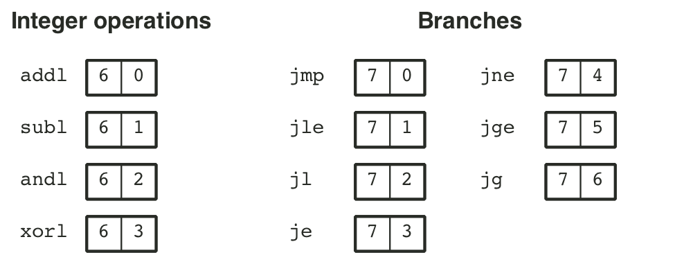
Figure 4.8: Logic gate types.
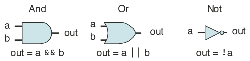
Figure 4.9: Combinational circuit to test for bit equality.
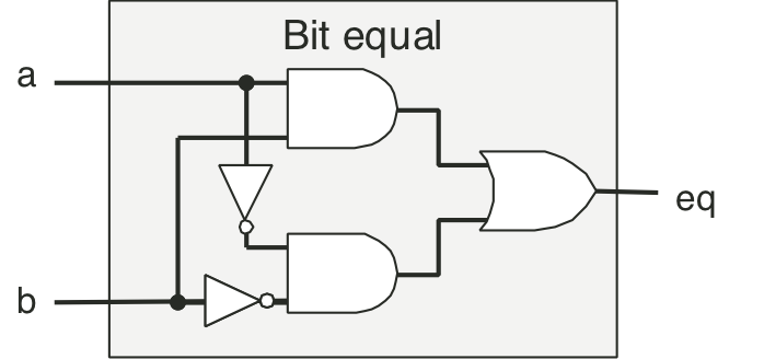
Figure 4.10: Single-bit multiplexor circuit.
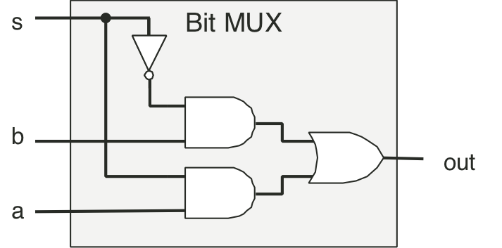
Figure 4.11: Word-level equality test circuit.
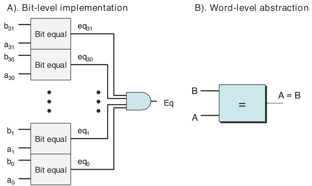
Figure 4.12: Word-level multiplexor circuit.
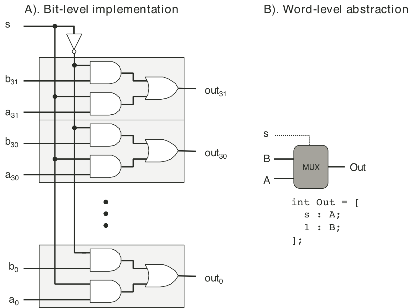
Figure 4.13: Arithmetic/logic unit (ALU).
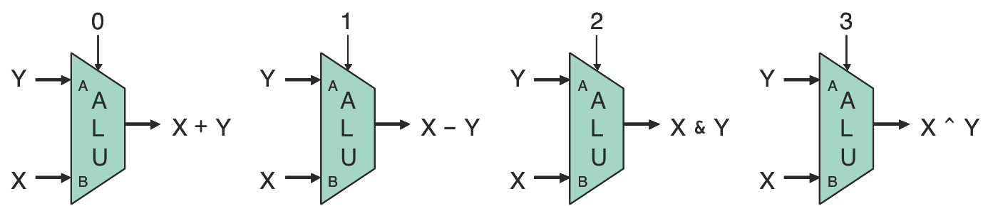
Figure 4.14: Register operation.
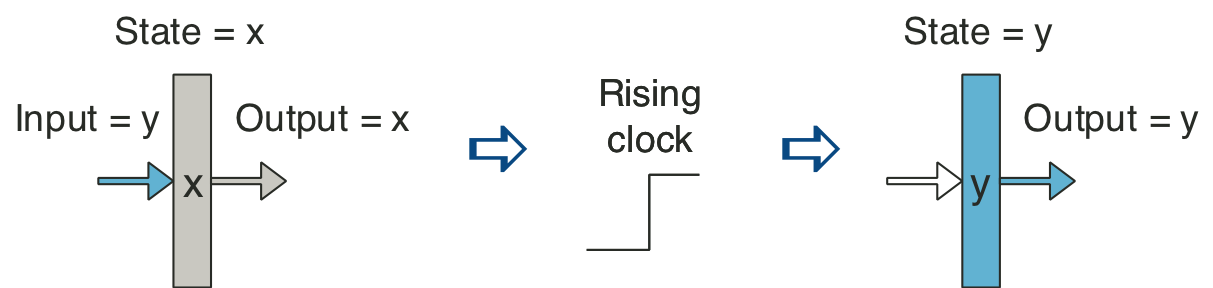
Figure 4.20: Abstract view of SEQ, a sequential implementation.
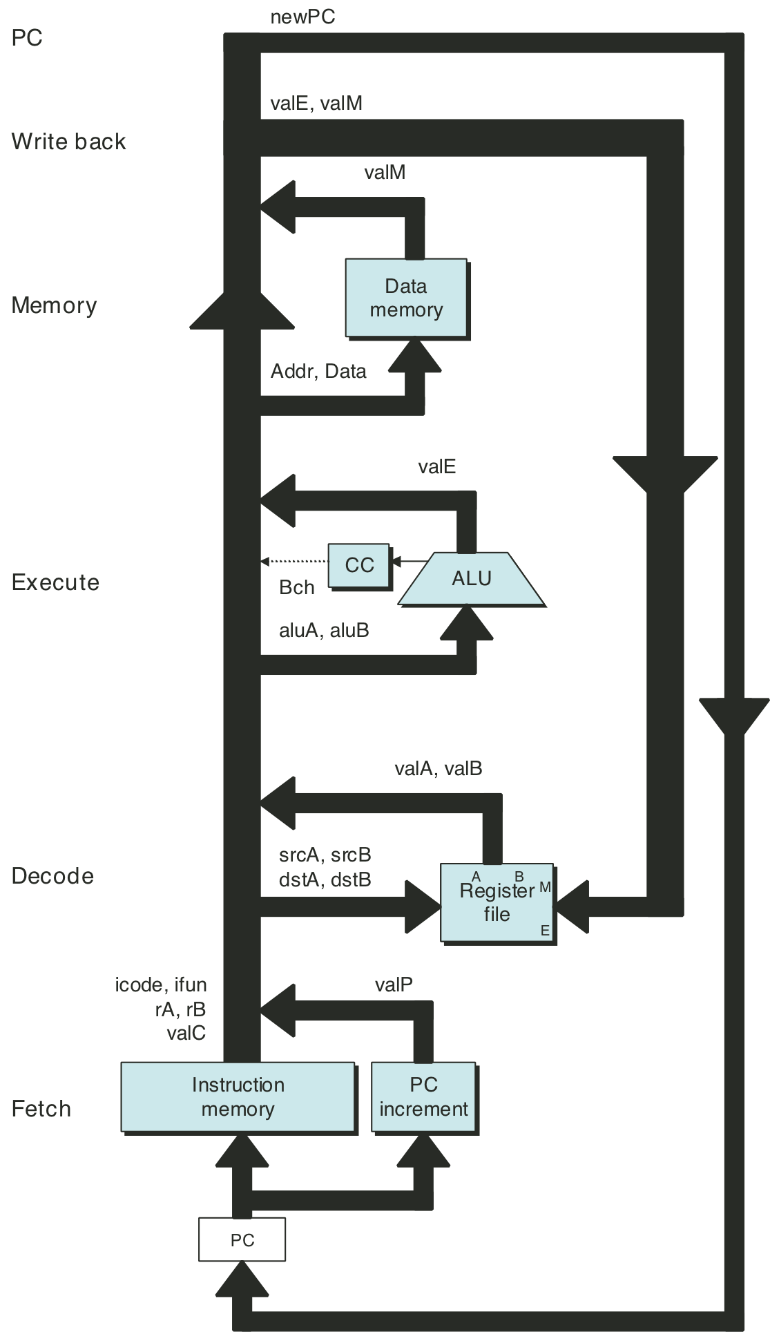
Figure 4.21: Hardware structure of SEQ, a sequential implementation.
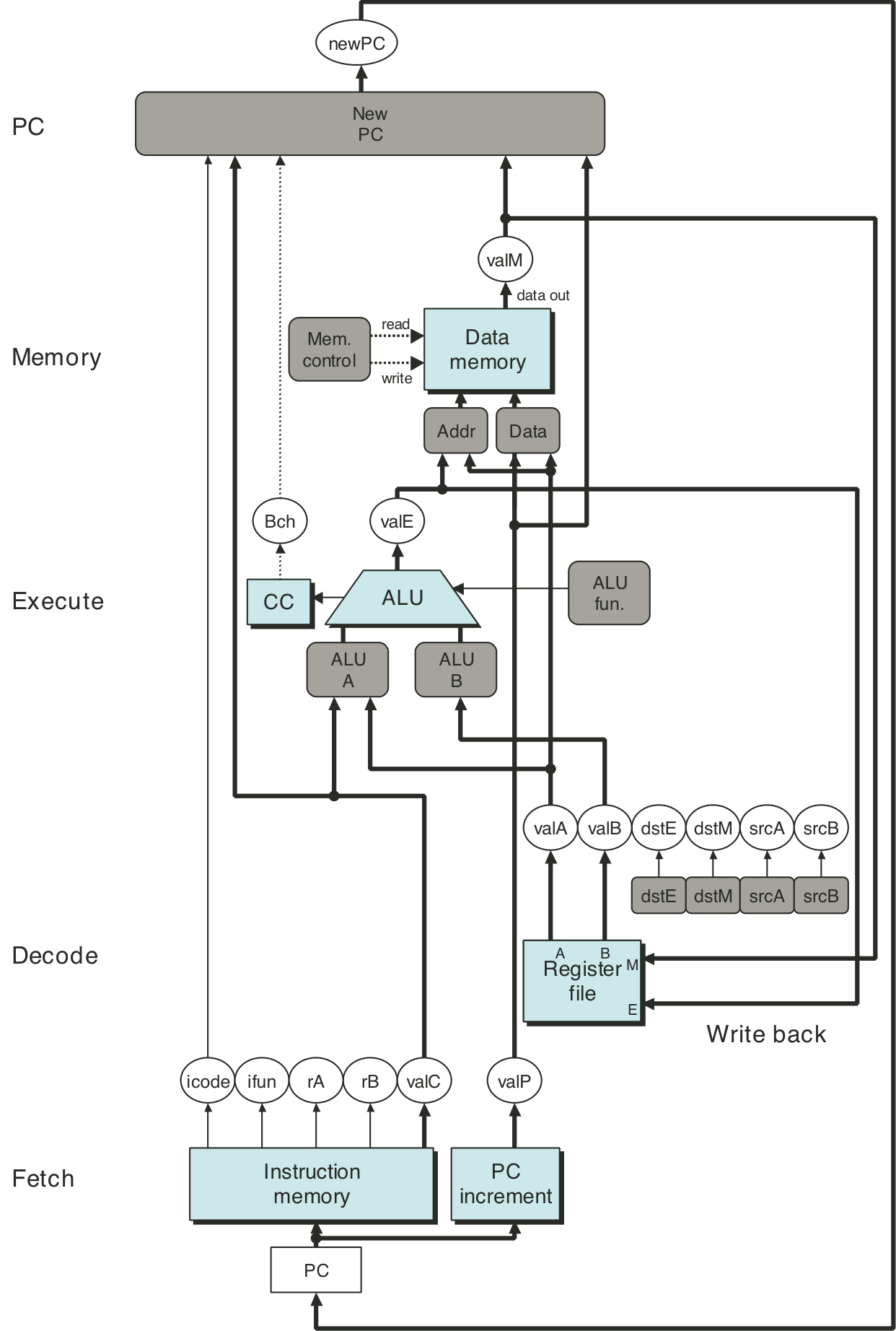
Figure 4.23: Tracing two cycles of execution by SEQ.
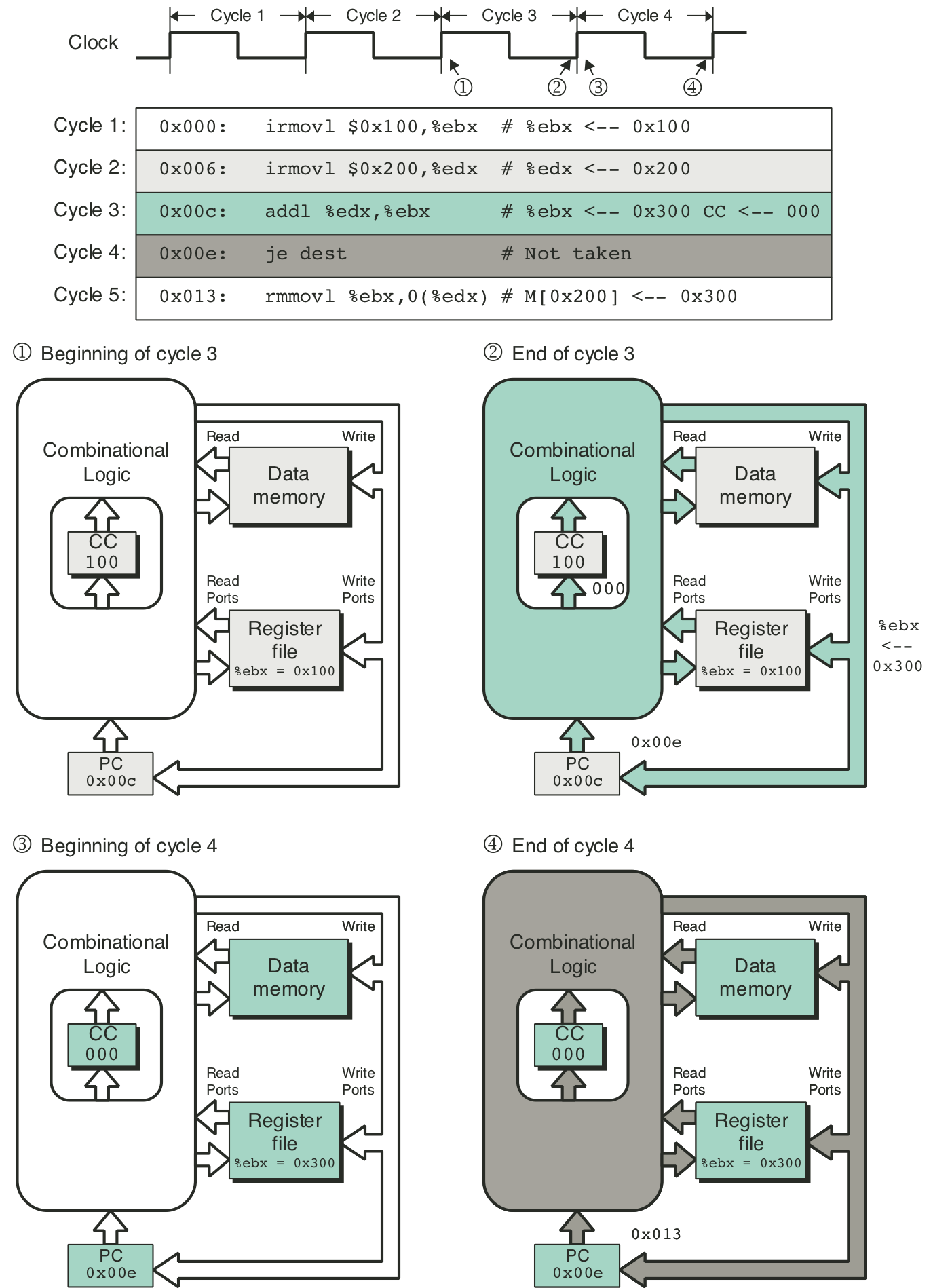
Figure 4.25: SEQ fetch stage.
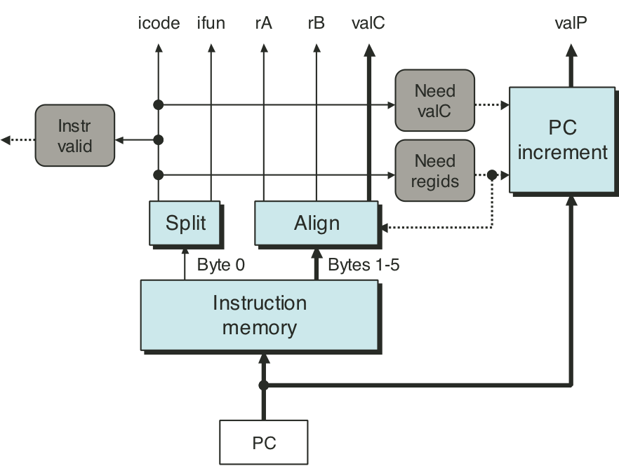
Figure 4.26: SEQ decode and write-back stage.
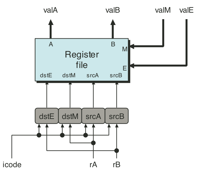
Figure 4.27: SEQ execute stage.
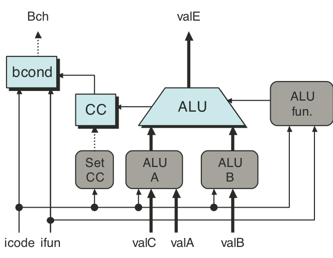
Figure 4.28: SEQ memory stage.
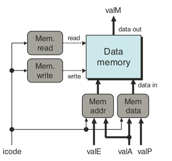
Figure 4.29: SEQ PC update stage.
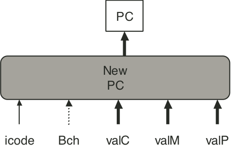
Figure 4.30: SEQ+ abstract view.
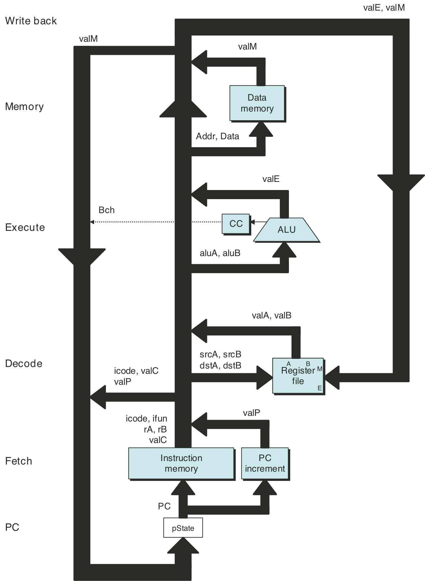
Figure 4.31: SEQ+ hardware structure.
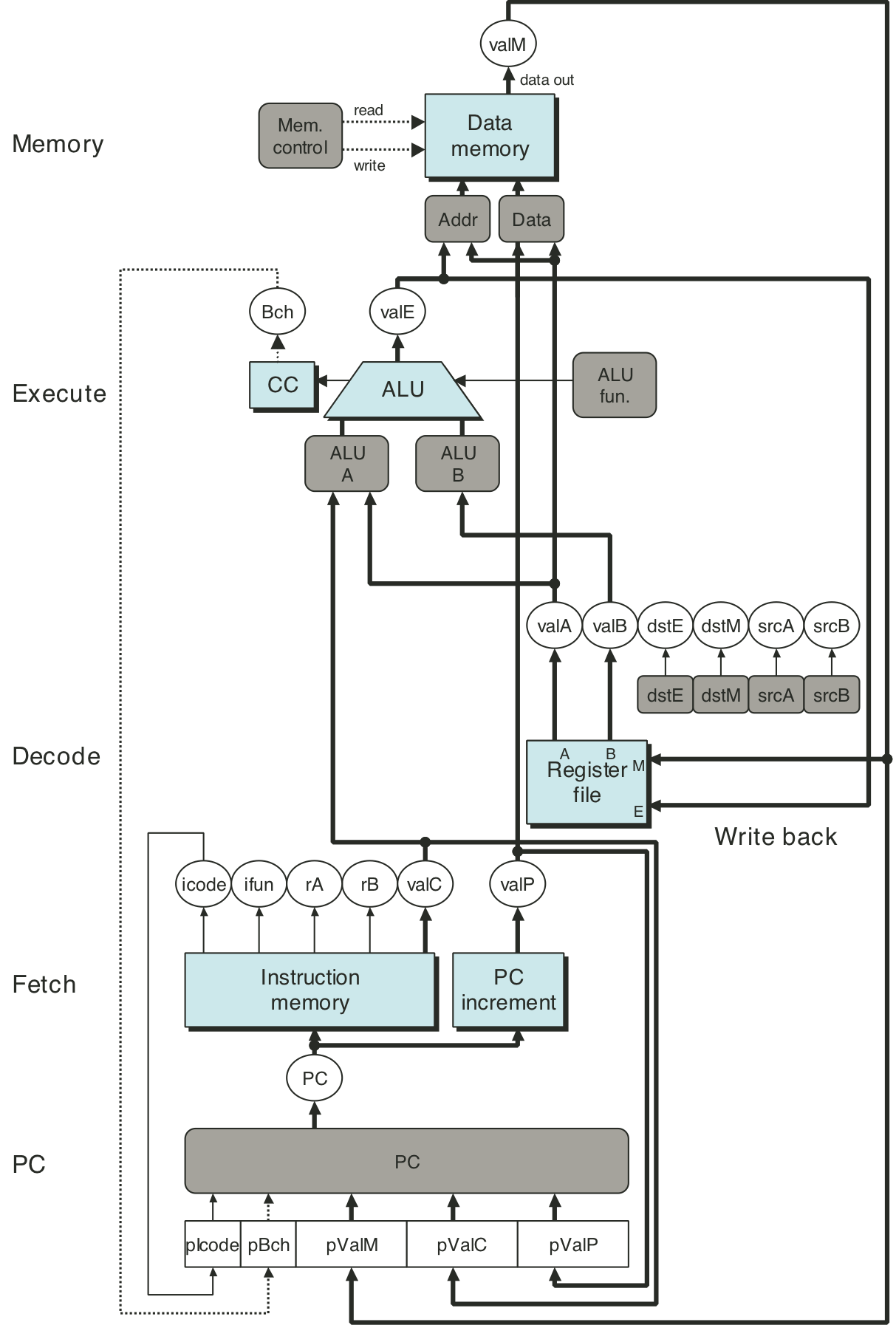
Figure 4.32: Unpipelined computation hardware.
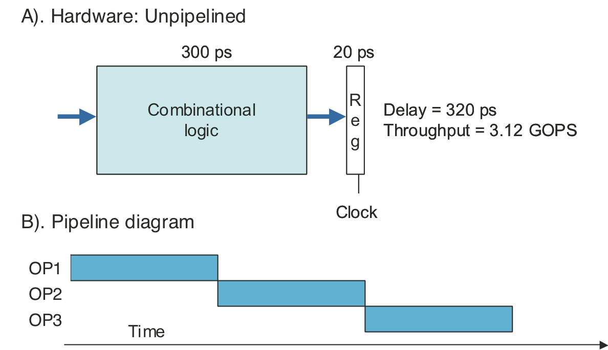
Figure 4.33: Three-stage pipelined computation hardware.
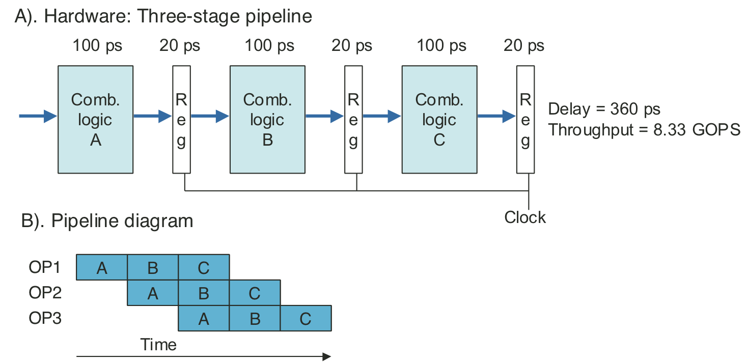
Figure 4.34: Three-stage pipeline timing.
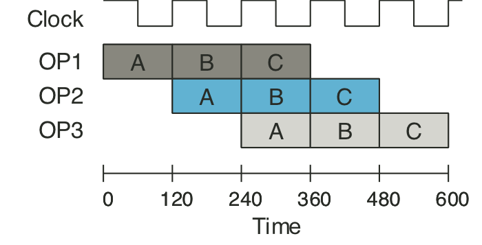
Figure 4.35: One clock cycle of pipeline operation.
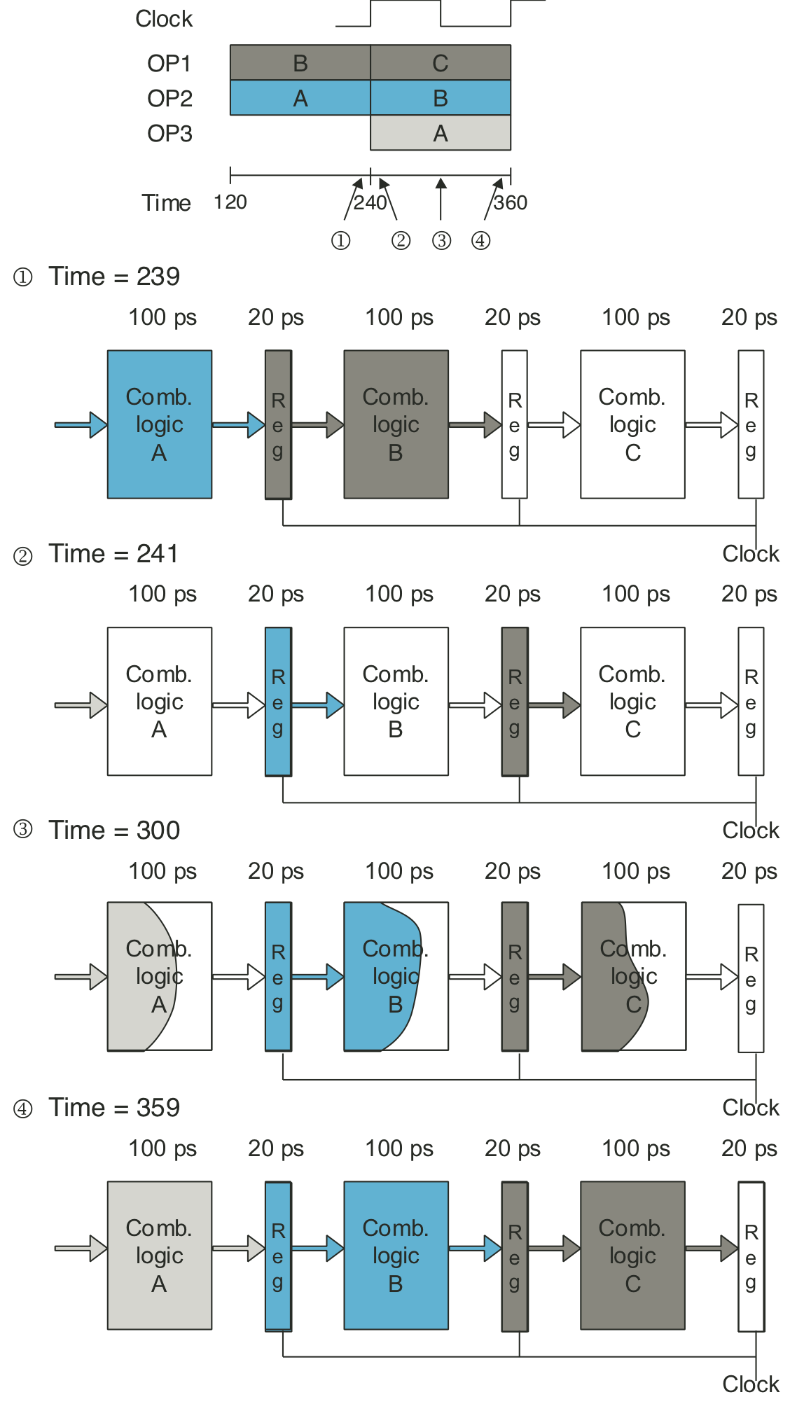
Figure 4.36: Limitations of pipelining due to nonuniform stage delays.
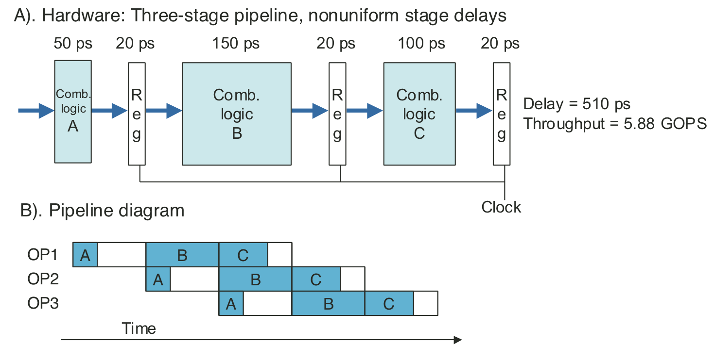
Figure 4.37: Limitations of pipelining due to overhead.
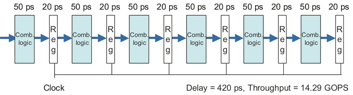
Figure 4.38: Limitations of pipelining due to logical dependencies.
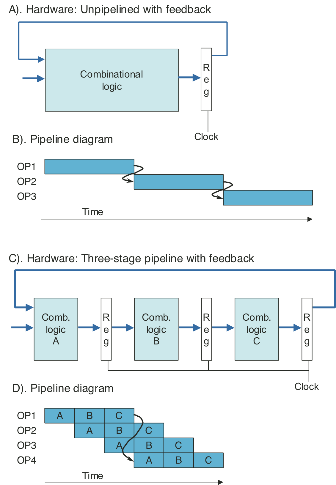
Figure 4.39: Abstract view of PIPE-, an initial pipelined implementation.
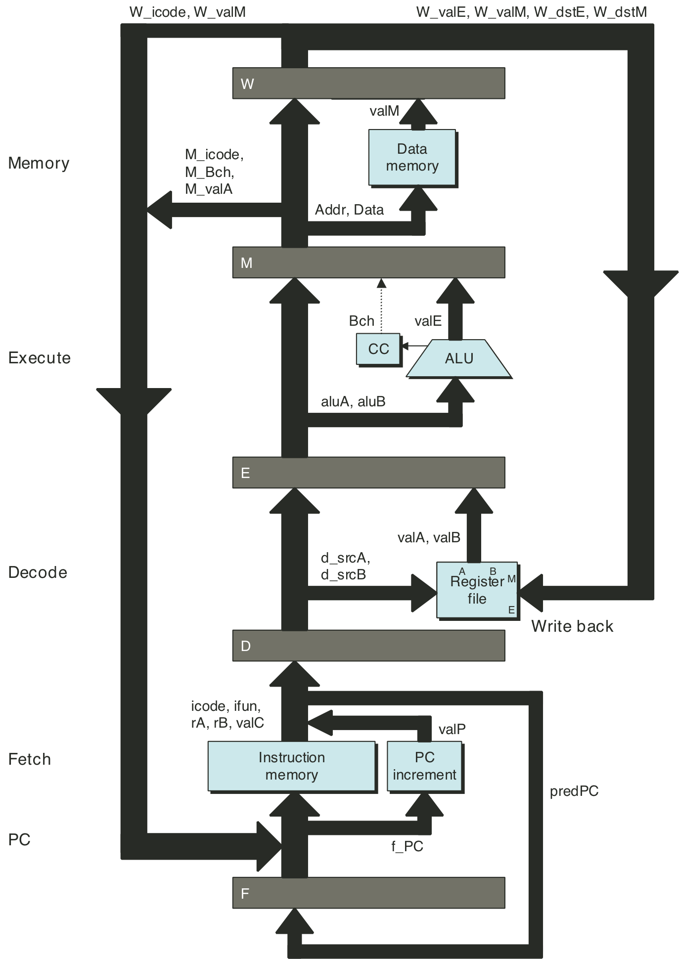
Figure 4.40: Example of instruction flow through pipeline.
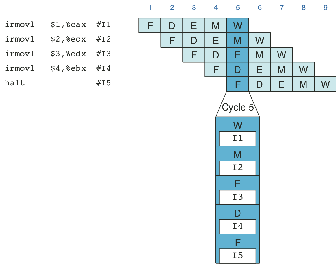
Figure 4.41: Hardware structure of PIPE-, an initial pipelined implementation.
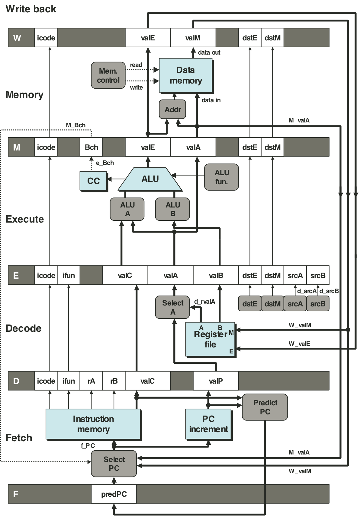
Figure 4.42: Pipelined execution of prog1 without special pipeline control.
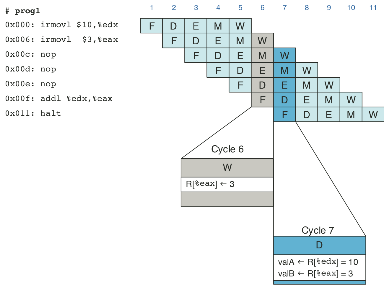
Figure 4.43: Pipelined execution of prog2 without special pipeline control.
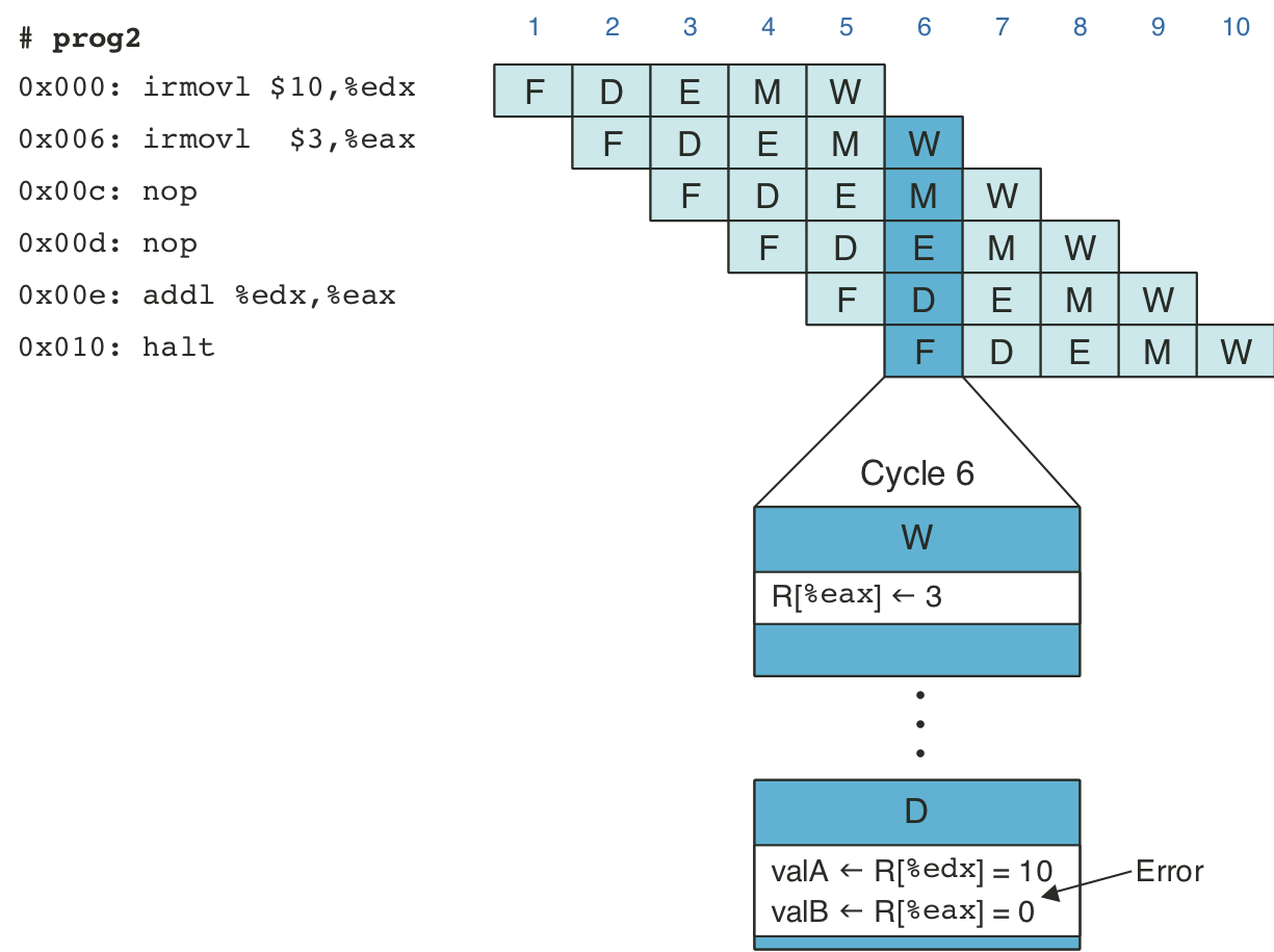
Figure 4.44: Pipelined execution of prog3 without special pipeline control.
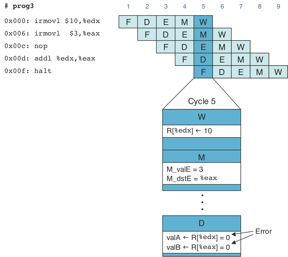
Figure 4.45: Pipelined execution of prog4 without special pipeline control.
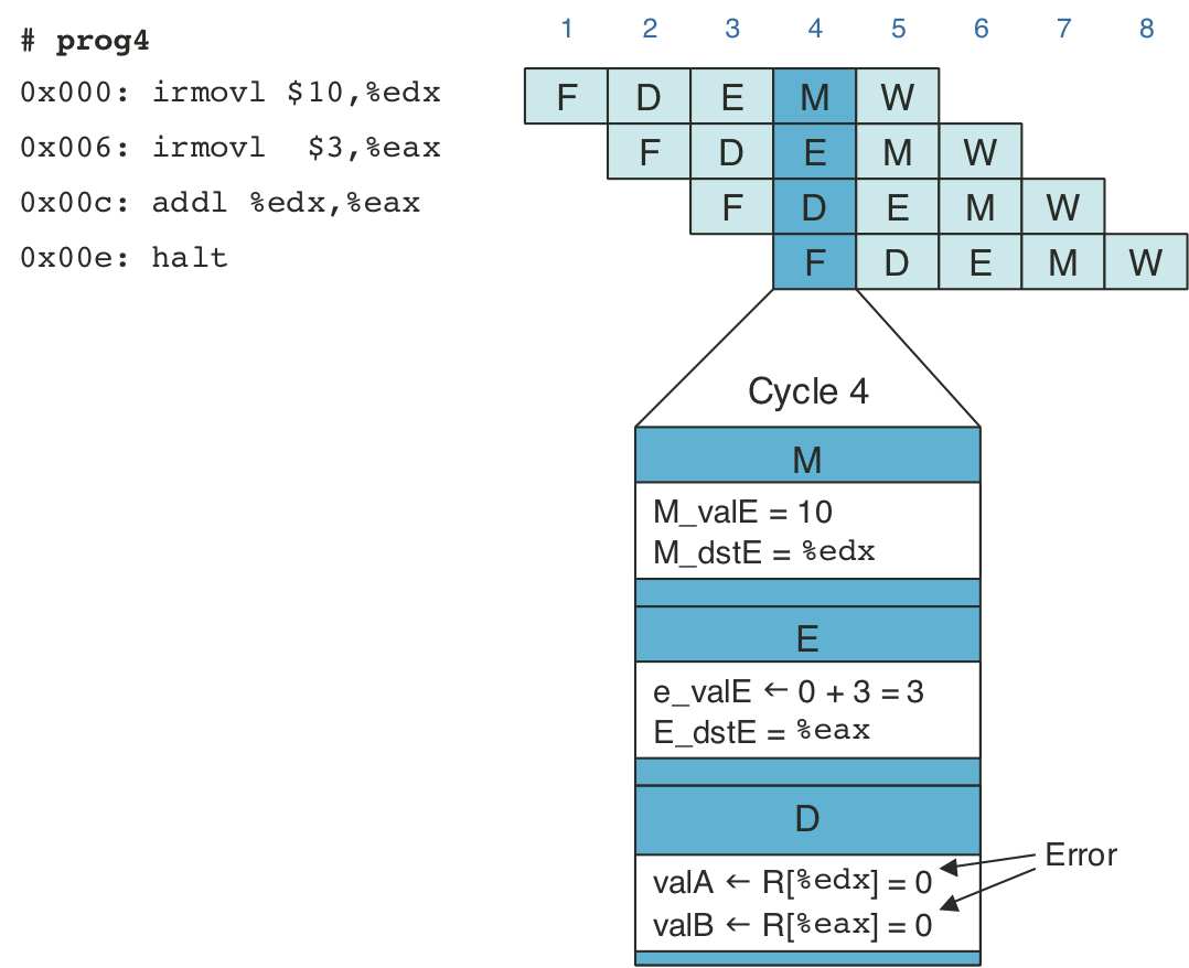
Figure 4.46: Pipelined execution of prog2 using stalls.
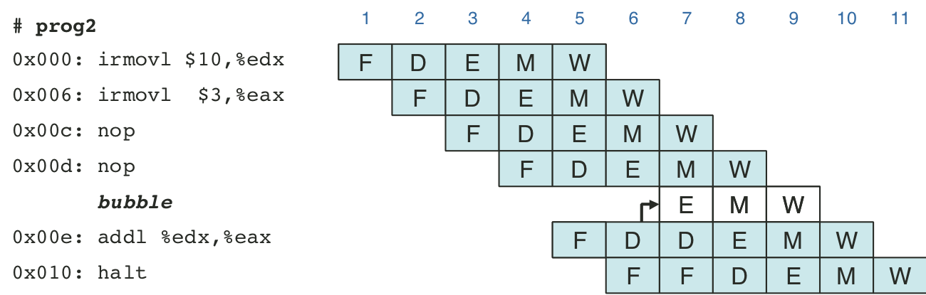
Figure 4.47: Pipelined execution of prog3 using stalls.
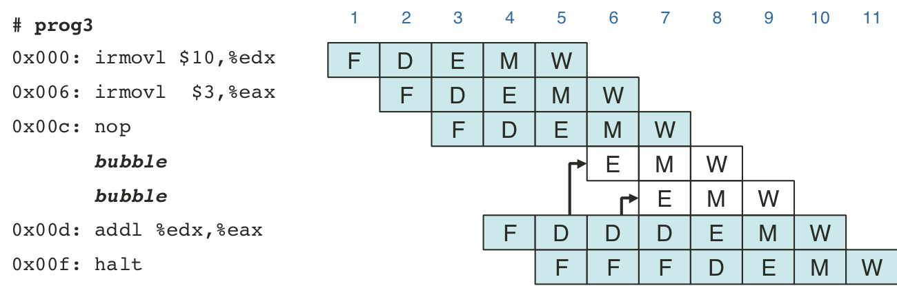
Figure 4.48: Pipelined execution of prog4 using stalls.
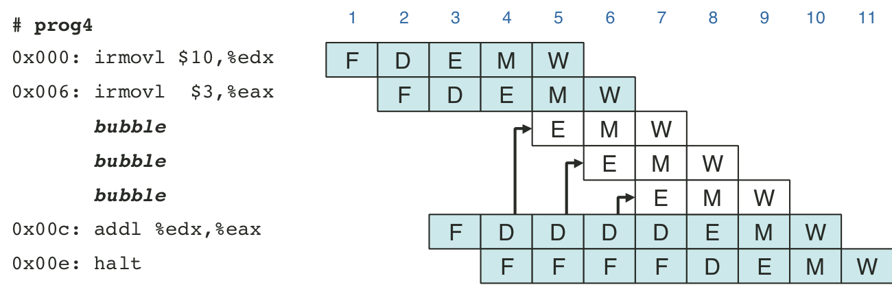
Figure 4.49: Pipelined execution of prog2 using forwarding.
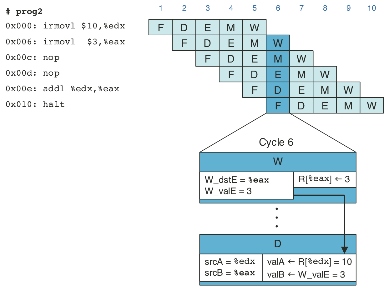
Figure 4.50: Pipelined execution of prog3 using forwarding.
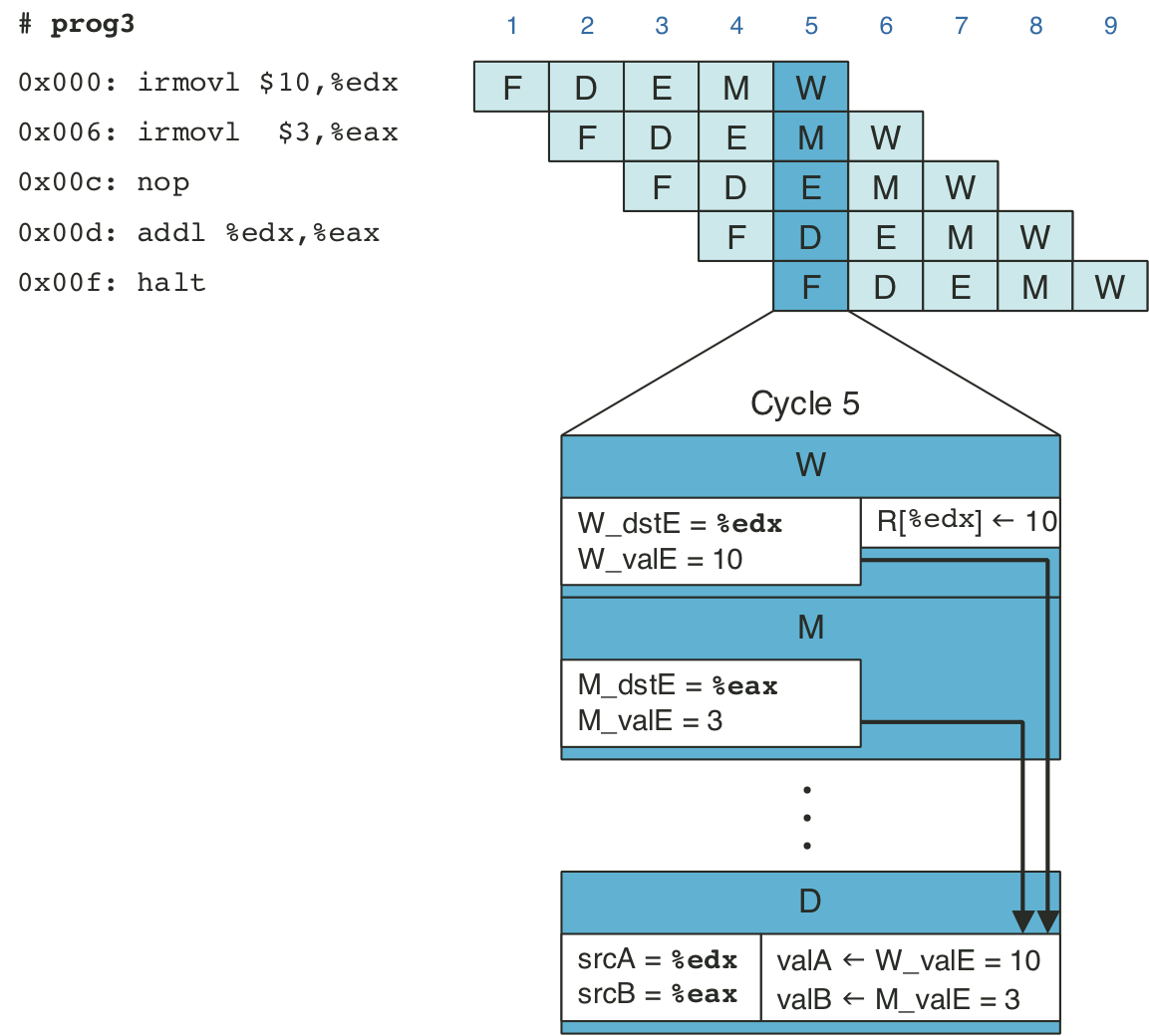
Figure 4.51: Pipelined execution of prog4 using forwarding.
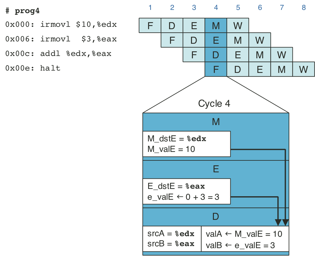
Figure 4.52: Abstract view of PIPE, our final pipelined implementation.
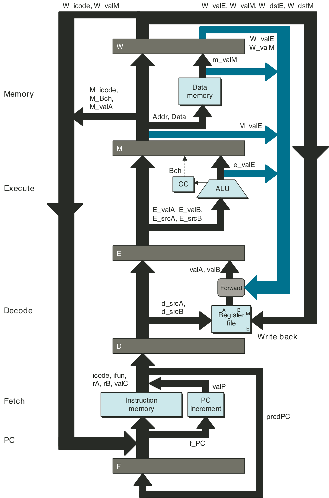
Figure 4.53: Hardware structure of PIPE, our final pipelined implementation.
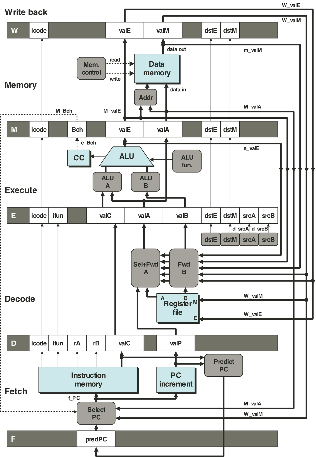
Figure 4.54: Example of load/use data hazard.
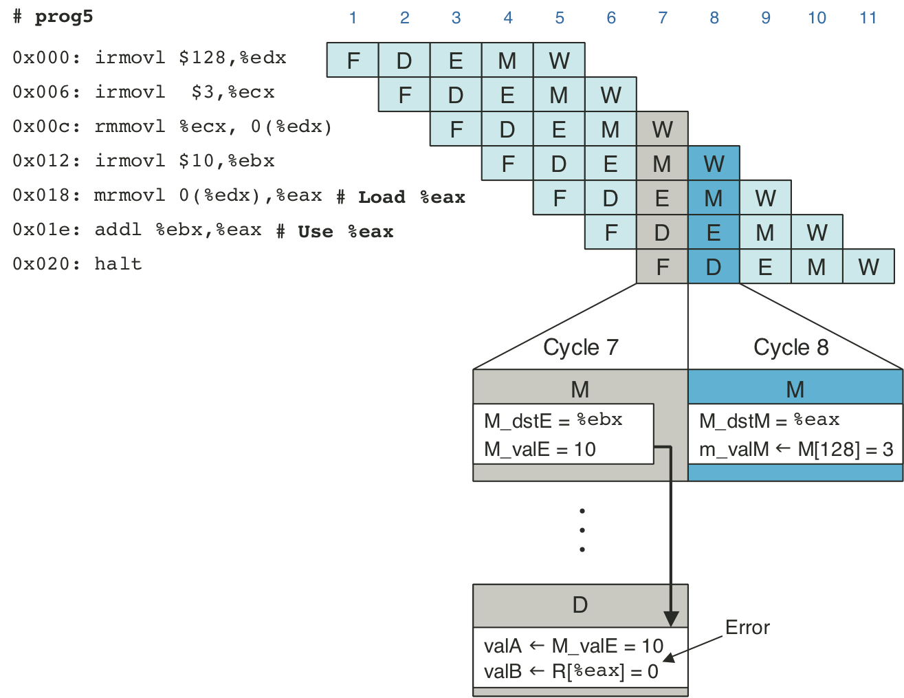
Figure 4.55: Handling a load/use hazard by stalling.
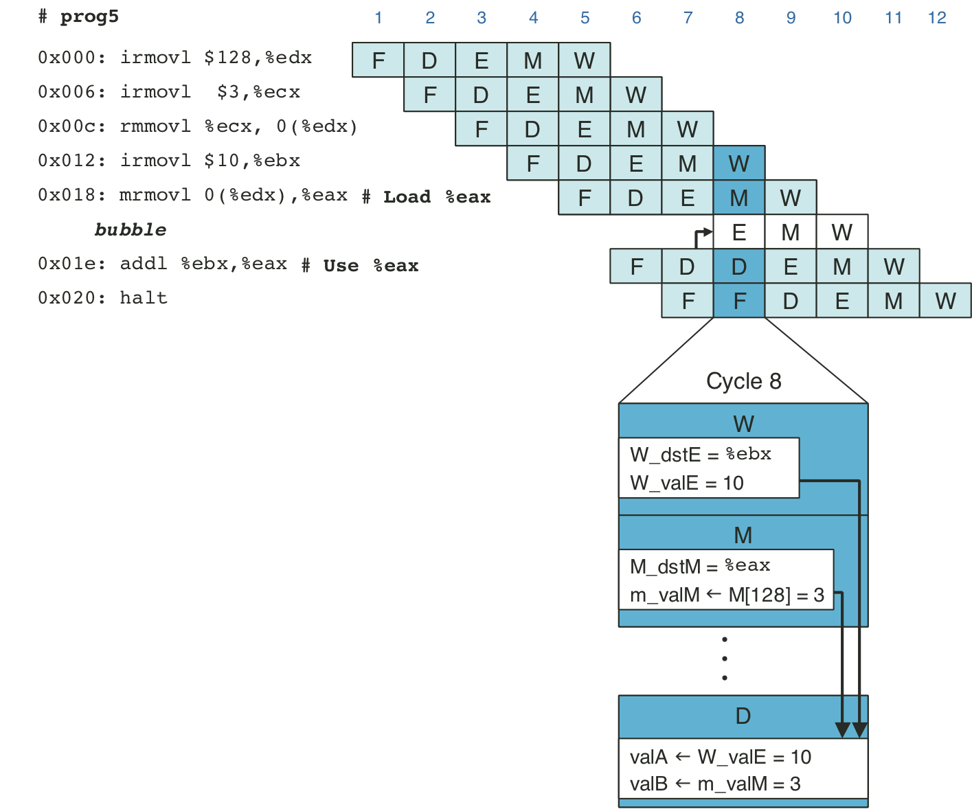
Figure 4.56: PIPE PC selection and fetch logic.
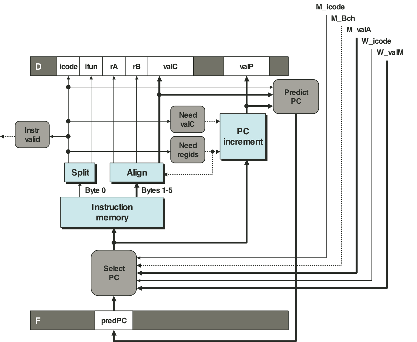
Figure 4.57: PIPE decode and write-back stage logic.
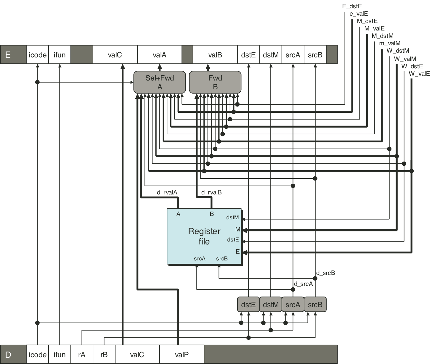
Figure 4.58: Demonstration of forwarding priority.
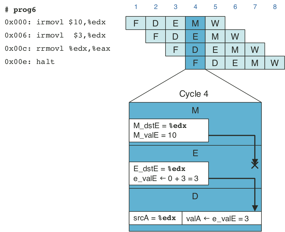
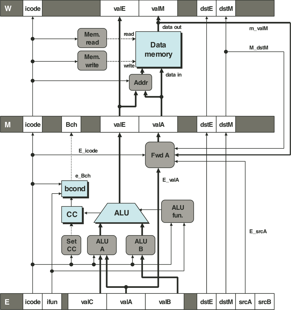
Figure 4.59: PIPE execute stage logic.
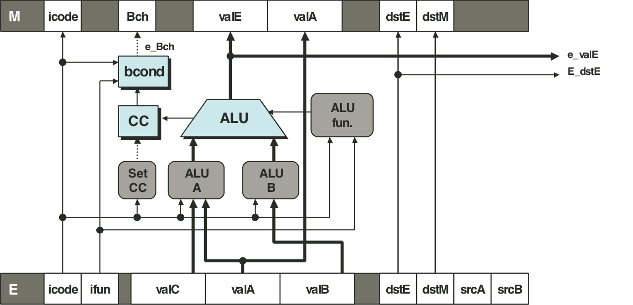
Figure 4.60: PIPE memory stage logic.
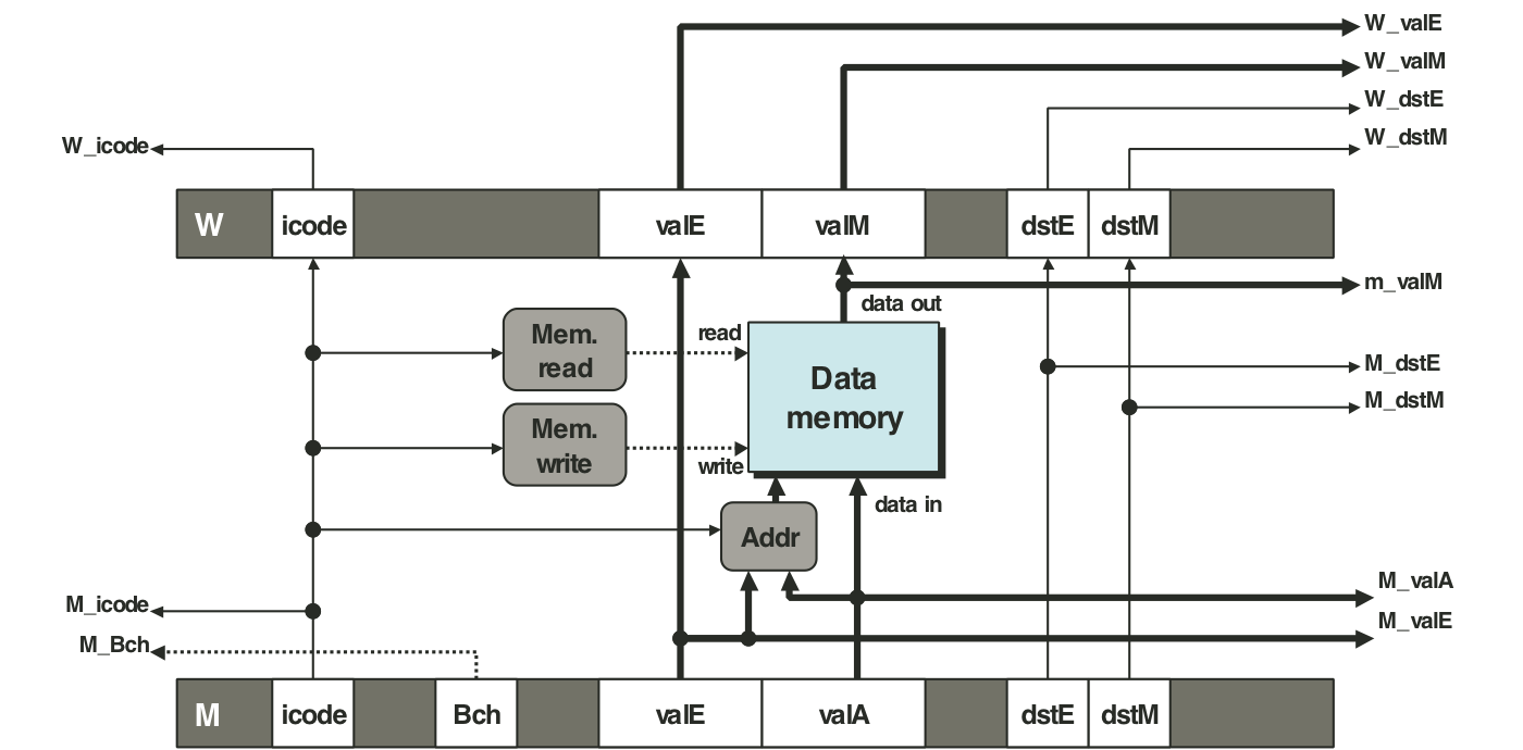
Figure 4.61: Simplified view of ret instruction processing.
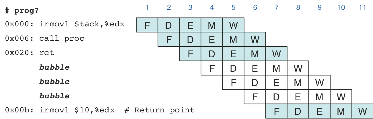
Figure 4.62: Actual processing of the ret instruction.
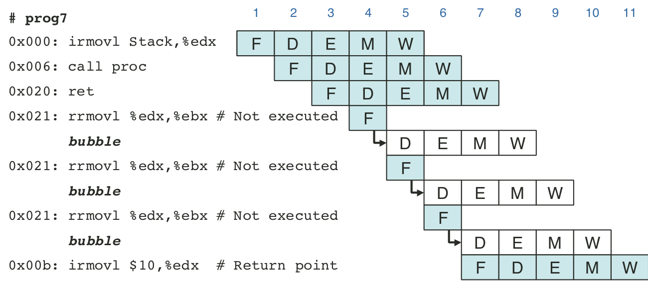
Figure 4.63: Processing mispredicted branch instructions.
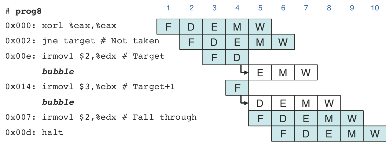
Figure 4.65: Additional pipeline register operations.
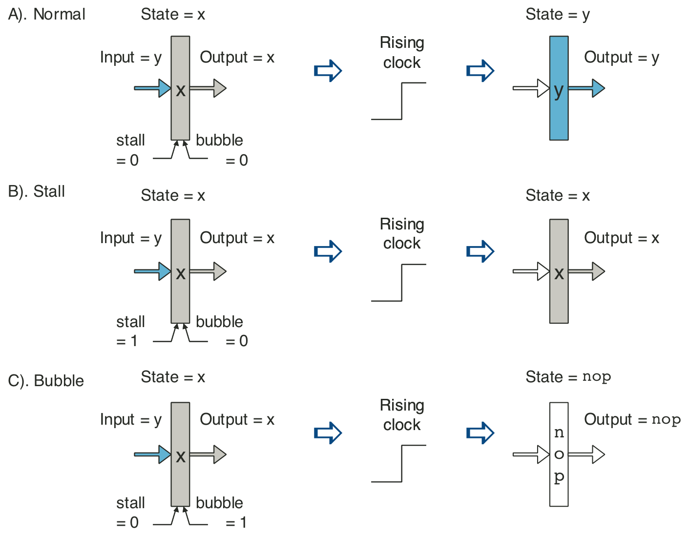
Figure 4.67: Pipeline states for special control conditions.
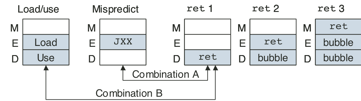
Figure 4.68: PIPE pipeline control logic.
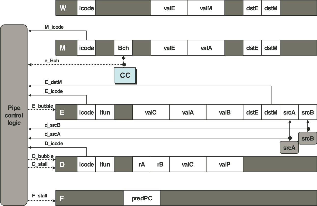
Figure 4.69: Execute and memory stages capable of load forwarding.